

According to ASME Y14.5 2009 GD&T standard, 14 geometric tolerances are divided into 5 groups. Circular runout belongs to the category of “Runout”, which is used to control the shape of the circular elements of the surface and their relationship with the reference axis.
In this article, we will introduce the definition of circular runout, its symbols, how to measure it, and the difference from total runout.
Definition And Symbol Of Circular Runout
Circular runout (often referred to as “runout”) is a 2D measurement of the circular profile of the reference axis. It checks how well the circular cross section fits the ideal circle, just like roundness.
Circular Runout Symbol
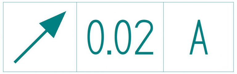
The runout symbol is a diagonal arrow pointing northeast (↗). It is a reference to how we measure the runout of a feature. We use a dial or height gauge to measure runout so the symbol actually represents the pointer in a dial gauge.
Round Runout Tolerance Zone
The tolerance zone is between the outer ring and the inner ring on the 2D plane. The circle in the middle represents the actual diameter of the shaft.
In GD&T, runout tolerance is used to control the position of a circular part feature relative to its axis. Runout is usually applied to parts with circular cross-sections that must be assembled together, such as drill bits, segmented shafts, or machine tool components. Runout helps limit the axis offset of the two parts to ensure that they can rotate and wear evenly.
An example of runout tolerance is shown below.
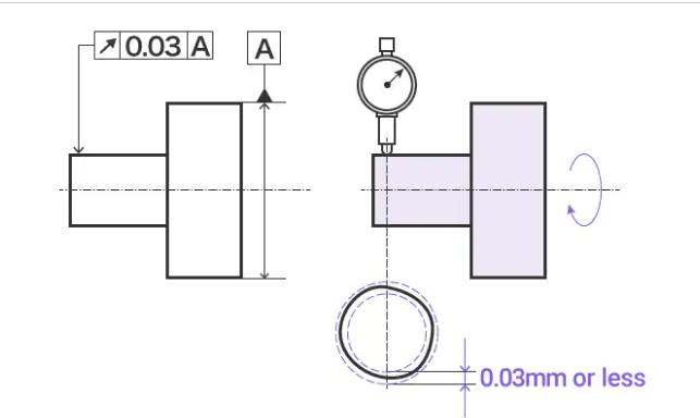
When the target rotates once on the reference axis, the radial runout of the cylinder surface (as indicated by the arrow) shall not exceed 0.03 mm on any measurement plane perpendicular to the reference axis.
The Difference Between Circular And Circular Runout:
The inspection process is similar to circular inspection. However, the difference between circular and circular runout is that there is no reference axis forcircular. However, it is necessary in the circular runout shaft.
Measurement Of Circular Runout
The measurement of circular runout is a typical process of cylinder operation. The parts are placed in a set of V-shaped blocks so that they can be rotated around an axis, and they can measure the total movement of a dial gauge that maintains a constant height at a circular position within a tolerance range.
Runout is measured using a simple height or dial gauge. We fix the part by means of a V-block or a spindle along its datum axis. The pin of a dial gauge is then set on the circular feature and the dial is set to zero.
We now rotate the CNC machined part along the spindle and record the measurements. The total variation on the height gauge must not exceed the tolerance limit in the feature control frame.
We can measure runout for surfaces that are parallel, angled, or perpendicular to the axis. In all cases, we hold the height gauge perpendicular to the surface. For each case, a two-dimensional tolerance zone is created in the direction of the height gauge pin. Then, as many cross-sections as needed are tested.
For surfaces that are perpendicular to the datum axis, we are testing flatness rather than circularity when we use this callout.
When using it for angled surfaces, we must remember to mention the basic angle, so we can set the height gauge exactly perpendicular to the surface. (source from https://fractory.com/circular-runout-explained)
Total Runout
In GD&T, total runout is a complex tolerance that controls the straightness, profile, angle and other geometric changes of features. The total runout is different from the runout because the total runout is applied to the entire surface at the same time instead of a single circular element.
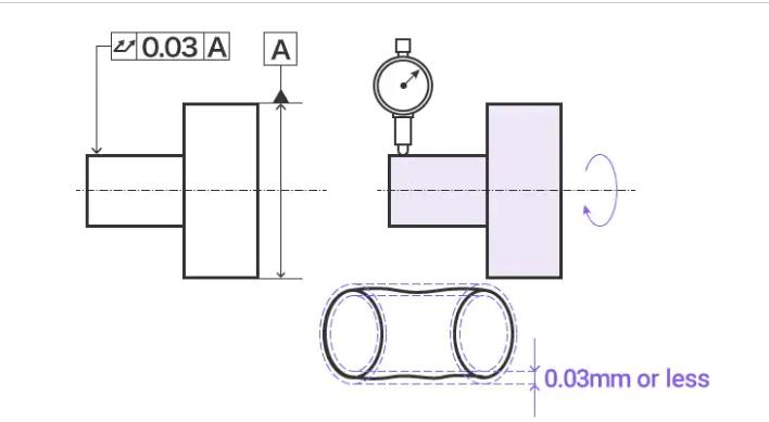
When the cylindrical part rotates along the reference axis, the total runout of the cylindrical surface in the radial direction (as indicated by the indicating arrow) shall not exceed 0.03 mm at any point on the cylindrical surface.
When To Choose Total Runout
The circular runout can effectively control the three parts. If the part has one of the following three functions, we use total runout control, or choose a more appropriate method.
Metal Parts With High Aspect Ratio
Parts with this profile, such as metal pipes, can be easily fixed in place and rotated to check the profile.
Sufficient length is essential to ensure that the degree of freedom (DoF) is limited for accurate inspection. This is the most effective ideal part of beating.
Parts With Small Diameter And Vertical Plane
If the length of the part is short and the diameter is small, but a vertical plane (for example, a flange) is attached, the circular runout can help us check the accuracy of the part.
Multiple Small Diameter Parts Separated From Each Other
An example of such a part is a concentric reducer. In such a part, the end of the part has multiple short diameters. Combine the two datum axes and use them as the main datum, instead of using one datum as the main datum and the other datum as the auxiliary datum.
Circular Runout vs Total Runout
Simply put, the total runout is equal to the 3D equivalent of the circular runout. The circular runout forms a circular tolerance zone around the curved surface (2D), while the total runout forms a cylindrical area.
In addition to setting tolerance limits on the cross section, the total runout also places it along the entire cylindrical surface to simultaneously control all cross sections of the feature under consideration. Therefore, it takes into account axial changes and cross-sectional changes.
Total runout can help us control more features than circular runout. It can control surface characteristics, such as:
Circle, concentricity, straightness, cylindricity, taper, parallelism, angle, perpendicularity, contour.
Related Post:
Introduction About GD&T – Circularity
Quick Guide To GD&T Parallelism
Introduction About GD&T – Flatness
Introduction About GD&T – Straightness