

In mechanical part drawings, vertical tolerances allow designers to specify the extent to which the orientation of right-angled part features may vary. Perpendicularity symbols are usually used on drawings to ensure that mating features can be assembled.
Verticality in GD&T can mean two distinct meanings, depending on the reference feature called. Normal form or surface perpendicularity is a tolerance used to control the perpendicularity between two 90° surfaces or features. The surface perpendicularity is controlled by two parallel planes as its tolerance zone. Axis perpendicularity is a tolerance used to control the perpendicularity of a specific axis to the reference plane. The axis perpendicularity is controlled by a cylinder surrounding a theoretically completely parallel axis.
Perpendicularity Description:
Surface Perpendicularity:
Surface perpendicularity is a two-dimensional GD&T mark used to control the perpendicularity between two surfaces. Perpendicularity can refer to 2D lines, but more commonly it describes the direction in which one surface plane is perpendicular to another reference plane. The vertical tolerances indirectly control the 90° angle between the parts by controlling where the surface must be located.
Surface perpendicularity is a tolerance used to control the perpendicularity between two surfaces that are aligned at 90 degrees to each other. It is controlled by two parallel planes as tolerance zones.
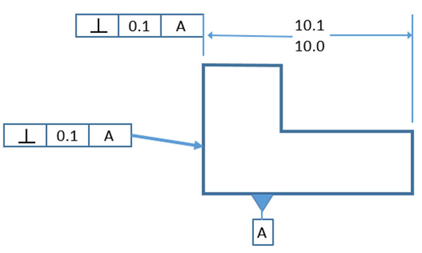
The surface vertical label above shows two ways in which the surface vertical label can be used as part of the dimension or directly associated with the feature. In both cases, we must also associate a data “A”.
Axis Perpendicularity:
Axis control can also be called verticality, which is one of the more common forms of axis labeling. When it is a circular feature reference, the feature control frame will contain the diameter (Ø) symbol. The feature can be positive, such as a pin, or negative, such as a hole.
Shaft perpendicularity is a 3D tolerance that specifies the boundary of the cylinder where the axis of the reference feature must lie. Used to control the perpendicularity of a specific axis to the reference plane, which is controlled by a cylindrical tolerance zone around a theoretically completely parallel axis.
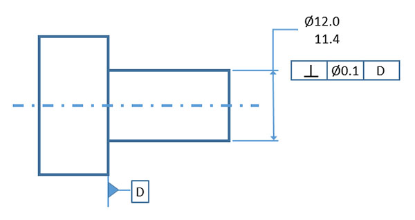
For the axis vertical dimension, we not only specify the perpendicularity, but also the diameter of the ideal cylinder in the tolerance zone. Therefore, the axis of the cylinder is perpendicular to the reference “D”.
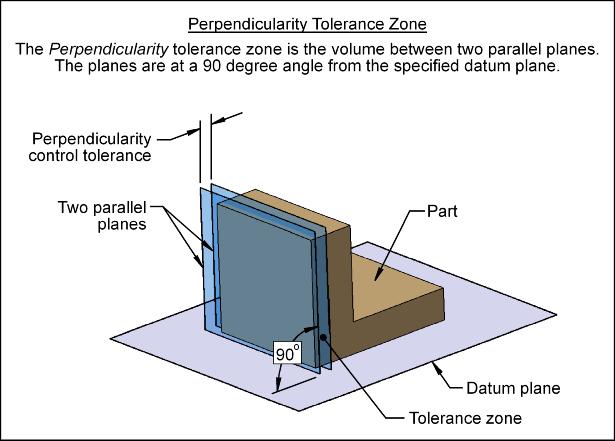
Perpendicularity Tolerance Zone
Surface Perpendicularity Tolerance Zone
The tolerance zone for surface perpendicularity consists of two parallel planes. The surface to be inspected must lie between the two planes to be approved. The feature control box controls the distance between two planes-the smaller the distance, the tighter the area.
As can be seen from the shape, this area does not directly control the angle between the two surfaces. Instead, it creates an area perpendicular to the reference plane and maintains the flatness of the vertical plane.
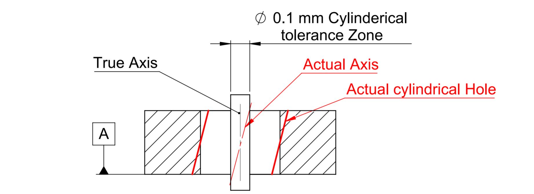
Axis Perpendicularity Tolerance Zone
Shaft tolerance zone perpendicularity For shaft perpendicularity, the tolerance zone is cylindrical, and the feature control box contains a diameter symbol to indicate it. The area is created around a theoretical axis that is completely perpendicular to the reference element. All points on the actual axis of the feature must be within the area to be approved. This allows it to be designed as a negative (hole) or positive (pin) feature, and additional tolerances can be considered.
Perpendicularity Measurement
When comparing them with other GD&T annotations, both the surface and axis perpendicularity are relatively easy to measure.
Surface Perpendicularity Measurement
An altimeter is required to measure the verticality of the surface. During the measurement process, the reference surface remains in contact with the plate.
The degree of freedom of the measuring tool (or part) is restricted by only allowing relative movement in the vertical direction. The deviation on the altimeter dial gives the verticality of the feature.
Axis Perpendicularity Measurement
Axis perpendicularity is usually measured with custom-made meters. These meters are constructed with the characteristic virtual conditions in mind.
Axis perpendicularity is usually called in MMC to ensure a good fit in all situations. Additional tolerances also play a role in defining the range of dimensions that will pass the tolerance check.
Perpendicularity Usage
Due to its simplicity and practicality, verticality is a very common notation in GD&T. Surface and axis perpendicularity are often used in engineering drawings to ensure the required perpendicularity.
In its surface form, verticality can control the plane and the curved surface. For example, it can ensure the verticality of the cylindrical surface relative to the bottom of the cylinder. It can also be used for center plane tolerances.
In its axis form, vertical can control the central axis of various front and back features. It is mainly used to ensure the verticality of the holes and pins to ensure that they fit perfectly in the assembly.
Related Post:
Quick Guide To GD&T Parallelism
Introduction About GD&T – Circularity
Introduction to GD&T: Circular Runout
Introduction About GD&T – Flatness
Introduction About GD&T – Straightness