

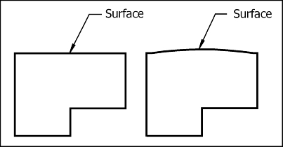
Consider the two surfaces shown. Which surface is completely flat? In fact, no surface is completely flat. How do we design a surface that is not completely flat but flat enough to function properly? Flatness control tolerance.
In this article, we will introduce flatness marking, tolerances, measurement methods, the difference between flatness and conventional tolerances and how to use it in the correct position to maximize efficiency.
Definition And Symbol Of Flatness
GD&T flatness is very simple. It is a general symbol, it indicates the flatness of the surface, and has nothing to do with any other benchmarks or features. It controls the extent to which the surface on the part may deviate from the ideal plane.
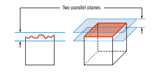
The tolerance zone for flatness tolerance is based on two parallel planes. A vertex located at the highest irregularity on the surface. The other is at the deepest point of any irregular surface. The controlled surface must lie completely in the space between the two planes. The distance between these two planes is the flatness of the surface. All points on the specified surface must lie between these two planes for part approval. The flatness tolerance applies to all drawing views, not just views that display tolerance annotations.
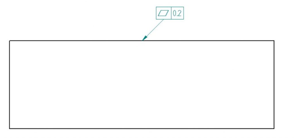
An example of flatness is shown below. Geometric feature symbol used for flatness. It is represented by a parallelogram, and the box symbol can be read as “The surface must be located between two parallel planes, 0.2 to each other in all views.
Tolerance Zone:
Two Sets of Parallel Planes where the entire referenced surface must lie.
Flatness Measurement:
Single Planar Surfaces
Flatness measurement requires a platform and an altimeter, probe or some type of surface. We can’t measure it by simply placing the part on a plate or a slab and using an altimeter, because this means that we have to measure the parallelism with respect to the bottom surface.
Using A Surface Plate
Machinists sometimes use panels to check flatness. Fix the part face down on the panel, and make the altimeter contact the designated surface through the hole on the panel.
Then, move the altimeter and parts so as to cover the entire length and width of the surface, and calculate the flatness variance of the actual surface.
Use A Coordinate Measuring Machine
Measurement of flatness, perpendicularity, and parallelism. Measurement of flatness, perpendicularity, and parallelism.
CMM can perform many different types of measurements.
Flatness And General Tolerance
Flatness And Parallelism
These two are often confused, but in fact they are completely different. Parallelism uses datums to control the surface, but there is no datum associated with “flatness”. One surface may be within the flatness tolerance, but not parallel to any other surface or datum.
Straightness And Flatness
Think of straightness as the 2D equivalent of flatness. Flatness is measured on a plane, while straightness is measured on a straight line.
Flatness And Surface Finish
Flatness and surface finish are usually in very different ranges, while surface finish is much better. Most surface finish measurements are some kind of average, and flatness is the worst case.
Benefits Of Using Flatness Tolerance
There are many different shapes and forms (literally) of engineering tolerances, each with its own nuances. Therefore, they have different applications and advantages. Flatness is no exception.
Flatness can control the waviness or variation of the surface without imposing stricter constraints on the surface.
We use flatness in parts where a good fit between two surfaces is important but the orientation of the part is not that important. Sometimes, designers use flatness to mark the entire surface with an equal amount of wear. This prevents any swinging when the parts are mated.
Using GD&T to specify the level of flatness will help ensure that the board meets your application requirements, whether it is ultimately used as a table or side board for a conveyor belt.
All in all, it is an easy-to-use tolerance that in many cases can help avoid any setbacks in the later stages of the project (assembly phase).
Related Post:
Introduction About GD&T – Circularity
Introduction to GD&T: Circular Runout
Quick Guide To GD&T Parallelism
Introduction About GD&T – Straightness
Fantastic