

In precision machining, the requirement of straightness is very important for parts, so this article will introduce straightness, mainly introducing the definition, symbols, tolerances, measurement methods and common problems of straightness.
Straightness (GD&T) Definition
Shape control can limit the deviation between the final shape and the ideal shape. GD&T straightness is one of the tolerances to ensure that the feature is close to the ideal state.
Straightness actually has two very different functions in GD&T, depending on how it is called. In its normal form or “Surface Straightness”, it is a tolerance that controls the form of lines on a surface or feature. Axis straightness is a tolerance that controls the number of curves allowed on the part axis. This value is usually called up by a call containing the maximum material condition. The two labels are very different from each other!
Surface Straightness:
The standard form of straightness is a two-dimensional tolerance, which is used to ensure that the part is uniform over the entire surface or feature. Straightness can be applied to planar features (such as the surface of a block), or it can be applied to the surface of a cylinder in the axial direction. Defined as the surface variance within the specified line on the surface.
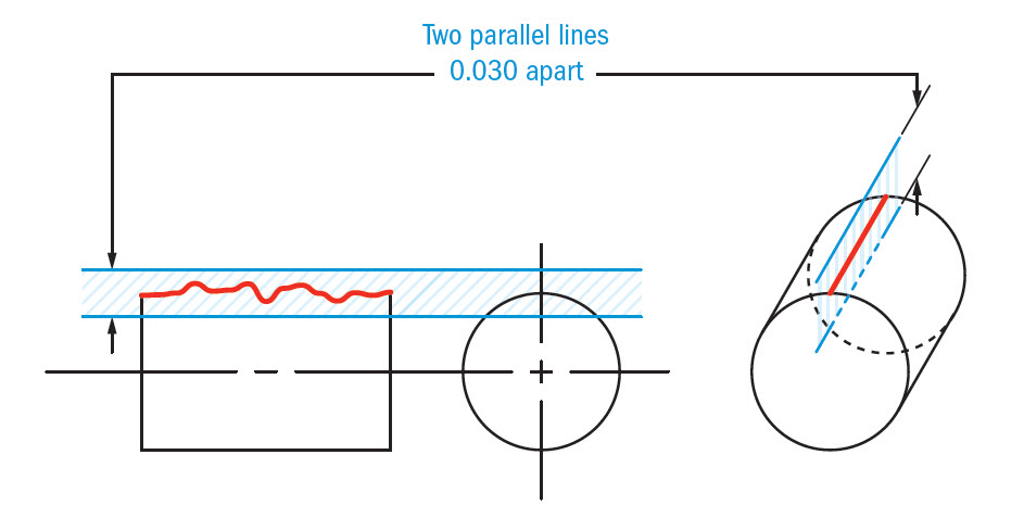
When we use this label to specify the surface flatness, the tolerance zone will form a total wide area above and below the ideal surface position and control all deviations. Surface straightness controls the form of lines anywhere on the surface, and there are two types of applications:
The first is a flat surface, such as the surface of a cube.
The second is the axial cylindrical surface. The Surface Straightness callout points the arrow to the surface and gives the tolerance.
In both cases, the tolerance zone forms a 2D plane. It appears as two parallel lines (also parallel to the surface), one above the surface and the other below the surface.
GD&T Tolerance Zone:
Two parallel lines on both sides of the surface line where the surface must be located.
Axis Atraightness:
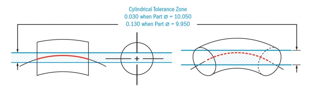
The straightness form of the central axis of the control part is sometimes called “axial straightness”. This tolerance marks the straightness of the axis (usually a cylinder) of the specified part. By definition, axis straightness is actually a 3D tolerance, which constrains the central axis of the part to prevent it from bending or twisting too far.
GD&T Tolerance Zone:
The cylindrical boundary around the true central axis of the part, and the derived midpoint axis of the part must be fitted into the boundary.
How To Measure Straightness?
The method of measuring surface flatness and shaft flatness is different.
Surface Straightness
Measuring surface flatness is very simple. The altimeter is fixed at a specified position on the surface and moves linearly in the direction indicated in the feature control frame.
Axis Straightness
Shaft straightness is usually measured using a cylindrical gauge, which is just larger than the diameter of the feature to accommodate the allowable variation. By using MMC annotations, we can ensure that the straightness and size ensure that the part always fits the hole of the given size. Therefore, if the outer diameter of the part is reduced, additional tolerances will be obtained, and the straightness of the part will be reduced accordingly.
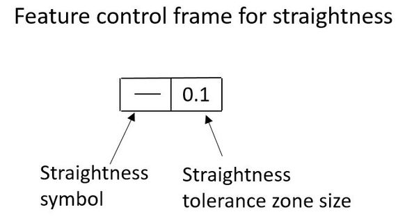
Instructions For Use
In a sense, surface flatness is a two-dimensional version of flatness. Both are measured without benchmarks, and both are used to control and refine the size of features. In the same way, we can think that “axis straightness” is related to “axis parallelism” and “perpendicularity” because they are all related to the central axis within the control cylinder tolerance zone.
Surface flatness is usually used for surfaces that must be mated with another part while providing a seal. Axis straightness (OTOH) is most often used when designing pins that must fit certain holes.
Why Use Straightness Tolerances?
When two parts in an assembly require line contact, straightness comes in handy. Using straightness, we mark the mating surface to pay special attention to it during processing.
Straightness control can be used to design and manufacture hydraulic sleeves, tubes and caps that require perfect contact to maintain high pressure.
Shaft straightness is used in the design of pins and cylindrical parts that need to be fitted into holes or holes to function. Straightness marking ensures that parts can fit even under maximum material conditions.
FAQ
What Is The Derived Median Line?
The derived median line is a line formed by connecting the midpoints at each cross section of the part. The meridian should meet the standard set by GD&T straightness control. If the part meets the tolerance requirements, the quality is qualified.
What Is The Bonus Tolerance?
Bonus tolerance are additional tolerances that take effect when the straightness dimension is marked with the Maximum Material Condition (MMC) modifier. In short, when the actual size of the part is different from the MMC size, the difference between the actual size and the MMC size will be added to the straightness tolerance value. This is the so-called additional tolerance.
In other words, as the pin size decreases to fit the hole, the straightness of the part needs to become smaller and smaller. This means that pins with pin, waist or bump shapes will still clear the pass/fail rules designed for them when they leave the MMC.
Related Post:
Introduction About GD&T – Circularity
Introduction to GD&T: Circular Runout
Introduction About GD&T – Flatness
Quick Guide To GD&T Parallelism