

What Is Parallelism in GD&T?
GD&T Parallelism Symbol
There are two types of Parallelism in GD&T. It can refer to surface parallelism or axis parallelism, depending on whether you are using it to control a surface or an axis. The use of surface parallelism is more common than axis parallelism.
For both types of GD&T parallelism, the goal is to maintain parallelism (0° alignment) to the datum element (axis or plane) according to the constraints specified in the feature control framework.
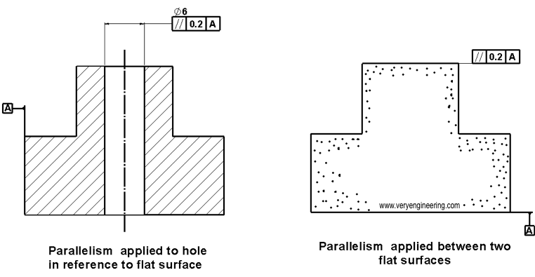
Parallelism is actually two different functions in GD&T, depending on which reference feature is called. Normal form or surface parallelism is the tolerance that controls the parallelism between two surfaces or features. The control of surface shape is similar to flatness, with two parallel planes as its tolerance zone. Axis parallelism is a tolerance that controls the parallelism of a particular part’s central axis to a datum plane or axis. The axis form is governed by a cylinder around a theoretical perfectly parallel axis.
Parallelism Tolerance Zone
Surface Parallelism Tolerance Zone
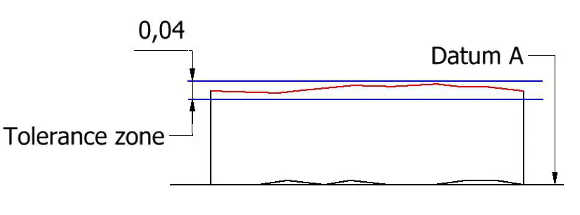
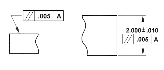
In the case of surface parallelism, the parallelism tolerance zone consists of two theoretically exact parallel planes. The distance between the two planes is the tolerance limit of the dimension. All points on the plane or center plane must lie in two parallel planes for the part to be approved.
Axis Parallelism Tolerance Zone
Axis parallelism creates a cylindrical tolerance zone. It is used to hold the axis of a dimensional feature, such as a pin or hole that is parallel to the datum. All points of the central axis of the feature must lie within this cylindrical area for the part to meet specification. In this type of zone, the allowable angular deviation can be controlled by reducing or increasing the diameter of the cylindrical zone.
Relation To Other GD&T Symbols
Parallelism and flatness
Parallelism and flatness are similar to each other on many levels. They all have similar tolerance zones. They basically control the flatness of the surface they are applied to. Their measurement method is the same.
However, there are some key differences that can help us differentiate the two. For example, parallelism, like all other orientation controls, cannot operate without a datum. Compare the slope of the surface to the datum plane to create tolerance zones.
On the other hand, when using flatness tolerances, the surface is measured in terms of itself. Tilt doesn’t matter as long as the flatness is within limits. With parallelism dimensions, regions can be translated or moved, but not tilted relative to the datum.
How to Measure Parallelism
Parallelism is easy to measure. Like flatness, gauges pass through a reference surface or feature. Unlike flatness, however, the part is constrained to a granite block or plane, which is used as a datum for measuring the part.
There are several ways to measure parallelism. The most commonly used method is the reference plate parallel measurement. In this method, components are placed on a flat base. Make sure the datum must be clean and accurate, depending on the level of accuracy you want.
The dial indicator then moves across the surface. Metrics must be within tolerance or the component’s parallelism fails.
If the tolerance requirements are very tight, make sure to measure at a consistent room temperature. Even small changes in temperature can affect this value, as some materials expand or contract with changes in temperature.
Related Post:
Introduction About GD&T – Circularity
Introduction to GD&T: Circular Runout
Introduction About GD&T – Flatness
Introduction About GD&T – Straightness