


The threads in the parts can sometimes eliminate the final assembly process, and in order to manufacture precise threads, we need to follow many thread design rules. This is a basic thread type, but it is also important. The main difference lies in the external threads of screws and bolts, as well as the external threads of hardware. The internal thread is located inside the main component and locks the screw and bolt threads.
Bolt Spacing
Once we consider the threads on bolts and screws, there is no one size applicable to all types. In addition to metric threads, the Unified Thread Series also includes major British threads such as UNC (coarse thread), UNF (fine thread), UNEF (extra fine thread). When you apply our system to assign specific threaded holes, the required pitch will come with it.
Thread Position
Usually, threads can be placed anywhere as part of your assembly requirements for turning or milling. As long as our equipment has access to that area. But if there are obstacles, our design analysis system will notify you which position cannot be threaded. It is always a good idea to follow our design guidelines in order to save your design time and costs.
Even if there are fewer restrictions on thread placement, the depth of internal threads is still a key factor to consider. Once the thread depth exceeds the maximum machining depth, the only method is to drill both sides of the hole and complete this process. In this case, there is another issue where the thread is not continuous from one end to the other.
For turning parts, we offer three types of holes to accommodate internal threads:
On the shaft: The hole passes straight through the center of the part from one end.
Axial: The hole is formed at one end through the part without a central area.
Radial: Holes are formed through the external behavior of the part.
Internal thread
We usually use single lip thread cutting tools to machine internal threads instead of traditional thread taps. You need to retain the guide diameter on the CAD model and remove the actual thread. We will analyze threaded holes in the following situations:
- The aperture is within the required thread range
- These holes are located on one of the three basic axes used for milling
- These holes are perpendicular to the turning rotation axis
- The position and manufacturing method of the hole will limit the qualification of the thread.
During the internal machining process, the hole depth may be longer than the maximum length of our threading tool. In this case, we will recommend some options based on your special requirements.
For long through holes that exceed the maximum extension range of the tool, please select the hole from the side where you expect the screw to start. Once your screw needs to pass through the entire part, you should use a tap in the hole to complete it as a secondary process.
You can also thread both sides of the feature, but pay attention to the maximum thread depth to avoid overlapping in the hole. Due to the risk of cross threading and the inability of screws to pass through the parts cleanly, there is a problem with the form of threads on both sides. It is usually good to choose threads from both sides, as long as the threads do not intersect.
There is an important consideration when creating threads for various diameters. Usually, we need to consider three measurement values: main thread, secondary thread, and pilot hole diameter. Once you instruct your manufacturer to mill a guide hole with the same diameter as the main thread, the hardware will never be installed correctly in the hole. It will fall in, and the screw will keep rotating in the hole. Its threads have nothing to crawl. In this case, you may need to choose larger hardware, but its functionality may not be acceptable or may not be consistent with your design. Therefore, you should ensure that any thread features of the guide hole reflect the minor diameter of the thread, and most CAD programs will help you complete this process.
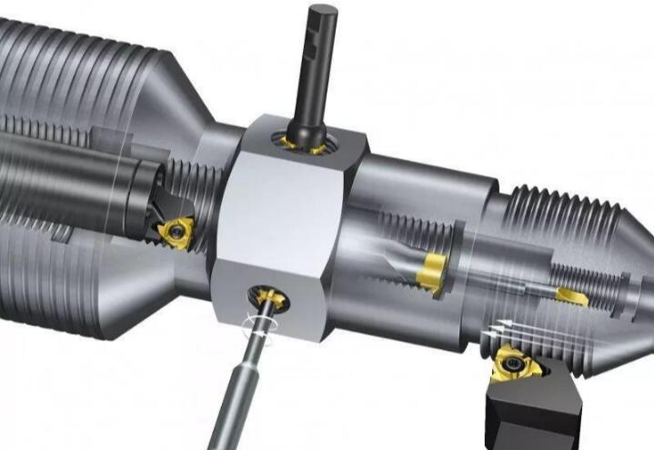
External Thread
As long as the parts meet the turning conditions, the external threads on the turned parts can extend the length of the parts. We usually use custom thread tools to select the position of thread size, depth, and part geometry. Our advanced turning technology provides external threads on the centerline of the parts.
Milling external threads is divided into two stages. The first set of threads is threaded halfway through the machined parts, and then threaded milling is performed on the other hand. These two edges intersect along the centerline of the part. In addition, we suggest removing excess materials and eliminating mismatches.
Small external threads are difficult to machine with ball heads or flat end mills because the pitch is too tight, leaving a larger radius at the root of the thread. You need to use a thread cutting mold for material removal.
Insert Alternating
For most metal parts, threads are the perfect way to firmly bond in component assembly. But for weak materials like plastic and aluminum, this band is not enough. This is where the application is inserted. Adding special coil inserts to plastic components will ensure a longer service life. This allows you to achieve strong threads on weaker materials. Basically, you can design a hole in the desired position and then add a blade. We will mill out holes for your insertion installation.
Thread is one of the very important applications of CNC machining centers, and the machining quality and efficiency of threads will directly affect the machining quality of parts and the production efficiency of machining centers. These features also have additional considerations and careful work to ensure final production according to design. Successful threads can sustain components for many years.