

Any part is composed of planes and surfaces. The measurement and evaluation of surface shape error is also a very important item in product inspection. In the mechanical manufacturing industry, the profile index is used to evaluate the error.
In this article, we will look at the profile of line tolerance and the profile of surface belonging to the profile group. Profile of a Line is very common, it helps us to manufacture parts with complex shapes. You will know the symbols, definitions, tolerance zones and precautions of Line profile GD&T Symbol:
What Is Profile of a Line in GD&T?
The profile of a line tolerance is a 2D GD&T dimension that defines and controls linear/curve features or surface cross-sections within specified limits. We can use it to control the form, position, direction and size of features. This dimension can only be used for surfaces, not for locating central axes or planes.
The line profile callout is usually used in the case of complex curves. These can be simple or advanced algebraic curves. If it is called on the surface, it is just like the radius on the part – the contour of the line will specify how much the cross section changes from the true bending radius. The profile of a line intercepts a cross section at any point along the surface and sets a tolerance zone on either side of the profile.
Line profiles are typically applied to parts with different cross sections, or to specific cross sections that are critical to part functionality.
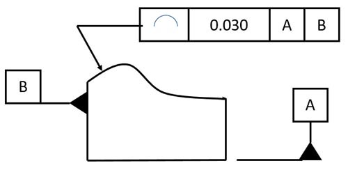
Marking of Line Profile Tolerance and Meaning of Tolerance Zone
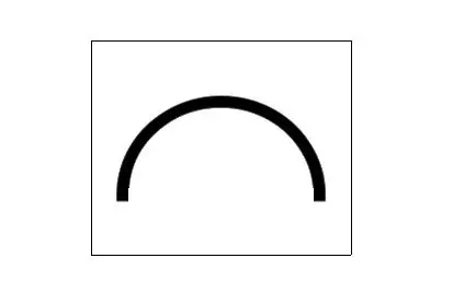
Line profile tolerance zone Line profile tolerance creates a true profile where the curve should ideally be located. The actual curve is evaluated based on this true profile.
The tolerance zone consists of two parallel lines that follow the true contour in either direction.
The distance between two parallel curves is the tolerance limit. Each point on the actual curve must lie between these two lines of the tolerance zone for approval. The application to which the tolerance zone applies can be specified on the drawing. The tolerance zone may or may not be referenced by the datum.
·No benchmark requirement
The tolerance zone is the area between two enveloping lines of a series of circles with diameter of tolerance value t, and the center of each circle is located on the ideal contour line.
·Having benchmark requirements
The tolerance zone is the area bounded by two envelopes of a series of circles whose diameter is equal to the tolerance value t and whose center is located on the theoretically correct geometric shape of the measured feature determined by datum plane A and datum plane B.
Remarks: When there is no datum requirement for line profile tolerance, it is a form tolerance, and when there is datum requirement, it is a position tolerance.
Relation to Other GD&T Symbols:
Profile of a line vs profile of a surface
The profile of the surface tolerance is most closely related to the profile of the line. In fact, it is the 3D equivalent of the line profile tolerance. The profile of a line controls a single line element on a single cross section or any other linear feature, while the surface profile controls the entire surface by taking into account changes in adjacent cross sections.
The profile of a line is used for advanced surfaces, such as when features bend on multiple axes at the same time. A common use of line profiles is to compare surfaces, such as car hoods or airplane wings. For aircraft wings, each cross section needs to have a different profile shape, and multiple measurements are required to ensure that the profile tolerance is met at each location. The profile of a line or the profile of a surface can be called on such surfaces.
Sometimes the contour of a line is used in conjunction with the contour of a surface. In these cases, the line profile tolerance will be more stringent than the surface tolerance. This ensures that the profile remains true along any particular cross section of the profile, while also ensuring that each cross section of the part is within a wider tolerance when compared together.
Profile of a line vs straightness/circularity tolerance
Straightness and circularity are used to control lines and circles, respectively. They are easier to measure and control, which can be done with simple measuring instruments. In addition to lines and circles, the contour of lines can effectively control highly complex curves.
In addition, straightness and circularity tolerances can only control the shape, while the contour of the line can control the shape, position, direction and size of the feature.