

Whether it is metal parts or plastic parts, CAD drawings are very important for designing and manufacturing finished products. Computer processing CAD drawings helps us solve these problems, but most designers or product developers may not fully understand the production process of the documents in the workshop How it is used, so in most cases, they will always provide one of them to request a quotation or manufacturing.
Today, from the manufacturer’s perspective, explain why we always ask to provide CAD drawings including 2D and 3D drawings together, so that you can use a computer to produce two different formats for us, so as to produce faster and more accurate precision parts that meet the requirements.
What is a 3D CAD Drawing?
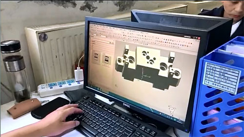
3D CAD is the abbreviation of Computer Aided Design. It is a technical system mainly used by engineers, architects and artists to design and produce technical documentation drawings. 3D software is used to make a data model that contains all the dimensional data of the part, even if it is not displayed on the screen at any given time. What you see on the screen usually looks like a solid object that can be rotated and viewed from any angle, providing the viewer with a deep perspective.
Some of the best 3D software includes UG, Solidworks, rhino, Catia, etc. The interaction between 3D CAD drawings and users is higher, and the 3D process has become very accurate and fast, which allows manufacturers to mass produce products. 3D CAD drawing is very effective software for our manufacturer’s production, which can help the manufacturer to produce different shapes in a very simple way.
How is the 3D CAD File Used in Manufacturing?
In machining part manufacturing, 3D files have some important purposes.
First, it can help the manufacturer understand the physical volume and geometry of the part, and understanding the size can help order raw material inventory. If this is a product assembly, we can see its product function and design purpose.
Secondly, because 3D files contain raw data, they can be used to generate cutting programs for any type of CNC machining process. In this case, the 3D model becomes a G code, which tells the path taken by the computer-controlled machine to cut the shape from the raw material. The CNC machine tool can mill and turn various shapes to complete the final finished product.
The 3D file can also help us calculate the exact part weight to check the volume and packaging of the product. We can know exactly how your product or parts will be packaged.
What is a 2D CAD Drawing?
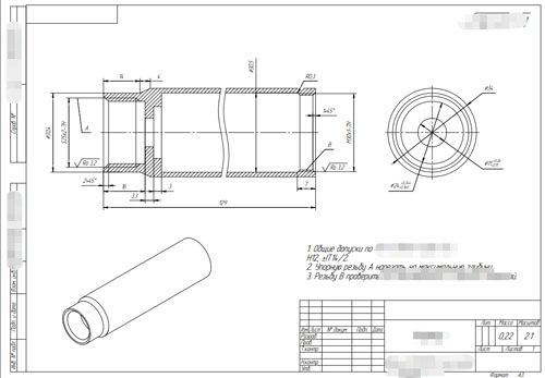
2D CAD drawing is a technique used by draftsmen to design, draw and edit technical illustrations. 2D CAD drawing is a two-dimensional line drawing that only shows one side of a part. Its working principle is similar to a snapshot of a part. 2D CAD drawings are mostly created digitally using graphics software, or can be directly exported from the 3D model with the click of a button. Designers usually need to make three different views to display the entire part, and some other details are needed.
How is a 2D CAD File Used in Manufacturing?
2D CAD drawings are the key points of our manufacturers. We can usually use 2D files to learn more detailed information about our products or parts. Every mechanical engineer must specify every important detail or area in order to tell the manufacturer All the important things about the part and how they want the part to look, feel, and function. All 2D CAD files should include at least:
- Physical dimensions and tolerances
- Hole size, location and thread type
- Surface roughness
- Surface finish and color
- Material type
- Corner radius
- Critical dimensions
For manual machining operations, the 2D drawing file needs to contain enough information to form all the features of the part. Skilled machinists are good at interpreting design drawings to make them into finished products by hand. For modern CNC equipment, this type of drawing is most commonly used to mark surface finish treatment and how to measure parts.
Only you (the designer) know how the part will be used and what its key functions are. Our design engineers and mechanical engineers need to understand how to use it for products, or the functions and uses of parts, and mark all this information as 2D engineering drawings. When these are clear, they can know what the final customer requires , So as to meet your expectations well.
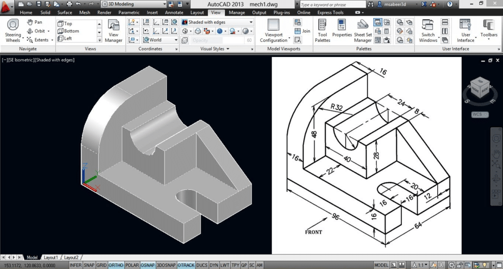
If only the 2D engineering drawings used to manufacture CNC machining parts are displayed, we still need to produce 3D files, which will reduce the time and cost of our manufacturers, so that we can quote and produce in a shorter time. Remember, when it comes to CNC machining, 3D files will be used to make parts and 2D to measure parts. (3D Compare To 2D CAD Drawing, What Is The Difference And Advantages?)
How to Get CAD Drawings
Now, CAD engineering drawings have become a standard in many industries, and there are now many free and paid CAD programs that can meet your requirements. Some of the best CAD programs available include SolidWorks and AutoCAD.
When it comes to the technical software, there are many design engineers who can make these files for you. CAD designers often have a deep understanding of CAD technology, which means that they can quickly and effectively create visual content suitable for your product, and can export the required 3D and 2D drawings as required to send to the manufacturer. If some suppliers have design capabilities, they can also obtain original CAD drawings from the current manufacturer and optimize the design from there.
Any CAD program should be able to create the necessary files needed, but each CAD program has its own file type. Although these native files provide great flexibility for the specific programs you use, not all files can be easily converted from one format to another.
Problems in converting CAD files will slow down the overall speed and can cause costly delays, so it’s important to understand the different file formats. (Related Post 6 Techniques For Importing CAD Drawings)
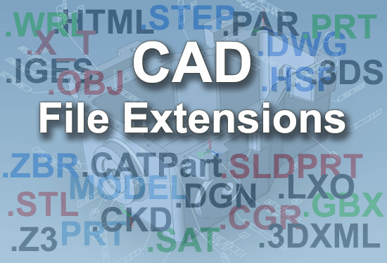
Common CAD File Formats Type
Native CAD file formats
The native CAD file formats of PTC Creo, Siemens NX, CATIA, SolidWorks, Autodesk Inventor and other formats are proprietary and require conversion and verification for downstream processing.
AutoCAD (.dwg): This is the most popular 3D CAD file format, is the original format. This is the native file format of the Autodesk AutoCAD program, which is the first widely used CAD program in this field. The extension is short for “drawing”, which is a compact binary format. In the header, it stores metadata such as file name, version, size, and style. In object data, it stores object entities and non-graphic objects, such as dictionaries. The file also saves object class and object mapping information.
Parasolid (.x_t): Parasolid is a geometric modeling program whose file extension contains the 3D CAD file information in the drawing, such as geometry, topology, and color. The coolest part is that .X_T files are exported as text files, which makes them easy to import and export to different CAD programs.
Neutral CAD file formats
 The neutral 3D format is very useful for sharing between different CAD programs. These 3D CAD file formats inherently collect less metadata than local CAD files, so some fine details are lost when using them, but they are great for collaboration.
Stereolithography or “Standard Tessellation Language” (.stl): Originally developed by 3D Systems, the STL file format uses rough triangles to describe the surface shape and area of a 3D CAD design. It describes raw data without specific units and is used for rapid prototyping, 3D printing and computer manufacturing. It is usually used in binary form to become more compact and can be used with various other CAD software.
STEP (.stp and .step): STEP stands for the standard of product model data exchange. It stores 3D images in ASCII format. Although the AMF 3D CAD file format stores more information, many manufacturing companies prefer to use STEP to price parts. Its ISO standard exchange can distribute 3D data so that it can be viewed through various CAD software. .stp and .step are interchangeable extensions for STEP files.
Initial Graphics Exchange Specification (.iges): It is a national standard CAD file format invented by the US Air Force. IGES enables users to exchange circuit diagrams, wireframes, free-form surfaces or solid modeling representations of product models. It is designed to automatically integrate all aerospace design files, and this function is now available for civilians who use traditional engineering drawings, analysis models, and other manufacturing needs.
It took me a while before I could finally find a CMS IntelliCAD software that is as good and easy to use as AutoCAD. What I appreciated most is that I can easily edit my .dwg files and it basically offers all features that I’m used to working with. Since CMS IntelliCAD gave me a free trial option, I tried to work with other software as well, including freeware, to compare and understand which one worked for me better. Out of everything I’ve tried so far, CMS IntelliCAD is definitely the best one in all aspects. Good job.