

If we can obtain electronic CAD drawings when we are dealing with projects, it will save us a lot of drawing process, which improves efficiency and accuracy. However, due to the irregularities of some drawings and other reasons, we do not always import the CAD drawings into the software smoothly. Then when the electronic drawing is found to be incomplete or incomplete, what methods and tips will be tried to successfully import it?
The CAD Drawing Is Very Small After Import
After the CAD drawing is imported into the software, the display is very small, even if it is maximized, the display is very small. However, it can be displayed normally when opened with CAD software. This is because there are other primitives in the CAD drawing. This primitive may be just a small dot or a short line segment, which is far away from the drawing we want to import. It can only be seen when viewed in full screen in CAD.
Solution:
Open the file with CAD software, double-click the scroll wheel in the middle of the mouse to display the full screen. At this time, you will find that in addition to the image we want to import, there is a small point in the interface. Drag the box to select and delete this point.
Misalignment Of Component And Grid
The grid has been identified and started to import the next drawing, column diagram, but after importing, it is found that the positions of the columns are all stringed, and they do not coincide with the identified grid positions. The coordinate origin of the identified grid is not the same as the coordinate origin of the imported drawing, so the imported column position is stringed.
Solution:
After the grid has been identified, the CAD drawings that will be imported in the future must be repositioned to ensure the accuracy of the import position of the components. Click and then use to capture a certain point of the newly imported CAD drawing. Generally, it is best to be the bottom left of the figure. , And then make this point coincide with the point at the same position of the imported grid.
Components Displayed Normally Cannot Be Imported Sometimes
After the CAD drawing is imported into the software, it can be displayed normally, but the components cannot be imported. Some CAD files use “external references”, that is, refer to the blocks on other CAD files. If you recognize such files, it may fail. Because although the walls, beams, slabs, columns, and axis lines can be seen, they are not part of the CAD file itself, so when reading the line data, nothing is obtained.
Solution:
Use the “External Reference Manager” under the AutoCAD “Insert” menu to find the blocks of which CAD files it refers to. The referenced CAD files are the real readable files. After you find it, select “bind” and save to recognize it.
The Identified Column Size Is Inconsistent With The Label In The CAD Drawing
The size of the identified column was found to be different from the label on the CAD drawing. At present, it has been found that there may be two reasons for this problem. The specific treatment method can only be determined by analyzing the drawings.
Problem Cause 1:
It may be caused by the proportion of the CAD file. The size of some icons is not consistent with the actual size. The software recognizes the components according to their actual size instead of marking the size during the process of identifying components. This causes the identified components to be marked with the CAD icons. wrong size.
Solution 1:
The first step after opening the drawing is to use the CAD query tool to query the scale of the drawing. Note: Do not query the dimension of the axis line! (Some drawings have been found that the dimension of the dimension is not proportional to the dimension of the column section), query the actual pixel and the dimension of the column, remember the ratio, for example, the actual dimension of the column is 3600mm , And the marked size is 5400mm. Then when importing CAD drawings, the ratio of actual size to marked size can be directly input 2:3. In this way, the size of the identified column is correct.
Problem Cause 2:
When the imported CAD project is large, the insertion point is too far away from the default origin of the system, which causes the size of the column after recognition to change. For example, the actual marked size is 400*400, but it is 600*800 after recognition.
Solution 2:
Open the file with CAD software, and then check the origin coordinates.
Customization Of CAD Importing Environment
Since it is often necessary to switch the display state of CAD in the CAD map, in some drawing states, the shortcut key F6 for displaying CAD graphics does not work. This is caused by the proportion of the CAD file. The size of some icons is not consistent with the actual size. The software recognizes the components according to their actual size instead of marking the size during the process of identifying the components. This leads to the identification of the components and the CAD icons. The size does not match.
Solution:
Click Tools→Options, and assign an infrequently used hotkey letter (such as: A) to “CAD drawing”. When you want to show or hide the CAD drawing in the future, just press “A”.
How To Import CAD With Many Drawings?
There are many drawings in a CAD file. How to import them at this time? Some CAD electronic drawings design all the drawings of the building or structure in a DWG file. The software can only import one drawing at a time, so there are many drawing software in a file that cannot be imported directly.
Solution:
Import the DWG file into the graphics software, and then drag the box to select the drawing to be imported. At this time, the selected part is displayed as a blue dashed line. Then, we drag the box to select all the drawings, because the software provides us with a reverse The function of selection, so when you select a picture and then select all in the drop-down box, at this time, except for the drawing we just selected, everything else is selected. Then click “Delete”. In this way, other images that do not need to be imported are deleted at one time. Import the selected drawing directly.
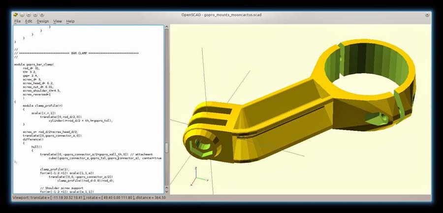
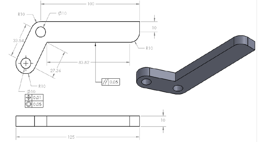
3D Compare To 2D CAD Drawing, What Is The Difference And Advantages?