First of all, we should know the role of the machined parts in the product, location, assembly relationship and working conditions, make clear the impact of various technical requirements on the assembly quality and performance of the parts, find out the main and key technical requirements, and then analyze the part drawing.
(1) Check the completeness and correctness of the part drawing
After understanding the shape and structure of the machined part, it is necessary to check whether the view of the part is correct and sufficient, whether the expression is intuitive and clear, whether the drawing conforms to national standards, whether the marking of dimensions, tolerances and technical requirements is complete and reasonable, etc.
(2) Analysis of technical requirements of parts
Parts of the technical requirements include the following aspects: machining surface dimensional accuracy, the shape accuracy of the main machined surface, the mutual position accuracy between the main machined surfaces. Roughness of the machined surface and other requirements for surface quality, heat treatment requirements, Other requirements (such as dynamic balancing, unrounded or chamfered, deburring, blank requirements, etc.).
Attention should be paid to analyze whether these requirements are economical and reasonable under the premise of ensuring the performance, and whether they can be realized under the existing production conditions. In particular, the technical requirements of the main surface are analyzed, because the machining of the main surface determines the general outline of the part process.
(3) Analysis of parts material
That is to analyze the mechanical properties and heat treatment of the blank material itself, the casting quality of the blank and the hardness of the material to be processed, whether there is white mouth, sand, loose and so on.To judge the degree of difficulty in machining and to provide a basis for selecting tool materials and cutting parameters.The selected parts materials should be economical and reasonable, with good cutting performance, and meet the requirements of service performance.
(4) Reasonable marking size
- The important dimension on the part drawing should be marked directly, and in the processing should try to make the process datum and design datum coincide, and in line with the principle of the shortest chain dimension.In Figure 1, the size of piston ring groove is an important size, and its width should be directly injected.
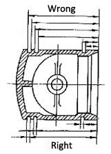
- The dimension marked on the part drawing should be easy to measure, do not mark the dimension from the axis, center line, imaginary plane and other difficult to measure the datum.The depth of the hub keyway shown in Figure 2 is easily measured with calipers or templates only if dimension C is indicated.
-
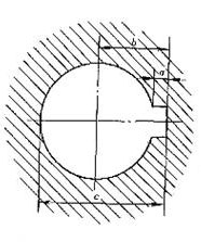
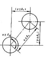
The dimensions on the parts drawing should not be marked into a closed, so as not to produce contradictions.As shown in FIG. 3, hole spacing dimensions A ± and Angle ± have been marked, so the x and Y axis coordinate dimensions cannot be marked randomly.Sometimes in order to facilitate processing, can be calculated according to the dimension chain, and marked in parentheses, as a reference size when processing.
-
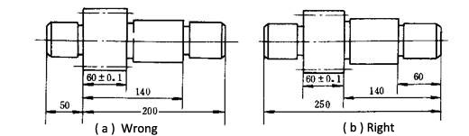
The non-matching free size on the parts should be processed in order as far as possible from the process reference notes.As for the gear shaft in FIG. 4, the representation method in FIG. (a) requires most dimensions to be converted and cannot be directly measured.The labeling method of Figure (b) is consistent with the processing order and convenient for processing measurement.
-
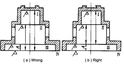
The position and size of each non-processed surface on the part should be marked directly, and there can only be one contact size between the non-processed surface and the processed surface.As shown in FIG. 5, the annotation method in FIG. (a) is not reasonable. Only one dimension can be guaranteed to meet the requirements of the drawing, while the other dimensions may be out of tolerance.Dimension A in the figure (b) be ensured when machining surface Ⅳ, other than processing the position directly tagging, guarantee during casting.