

The view of a part only represents the structural shape of the part. The size and relative position of its components, like the assembly, are determined according to the dimension values marked on the view.
The dimension on the part drawing is an important basis for processing and inspecting parts, and is one of the important contents of the part drawing. If the dimensions are wrong, it will bring trouble to the manufacturing of parts, and even cause production losses. The dimensions on the part drawing must be correct, complete, clear and reasonable. The rationality of dimensioning requires that the dimensions marked on the drawings not only conform to the design requirements of the parts, but also conform to the actual production, facilitate processing and measurement, and facilitate assembly. However, in order to achieve reasonable dimensioning, more knowledge of mechanical design and process is required. Here we only introduce some preliminary knowledge of reasonable dimensioning.
Reasonable Selection Of Dimension Datum:
The starting point of dimension is called dimension datum (abbreviated as datum). Generally, the face (such as end face, bottom face, symmetry plane, etc.), line (such as axis), and point on the part are selected as the datum. There are two kinds of dimension datum on parts, namely design datum and process datum.
From the design point of view, some benchmarks selected to meet the specific requirements for the structure and performance of parts in machines or components are called design benchmarks. The design basis determines the location of parts on a machine or assembly.
From the perspective of processing technology, some benchmarks selected to facilitate the processing, measurement and assembly of parts are called process benchmarks.
In order to reduce the size error and ensure the product quality, it is better to unify the design datum and process datum when dimensioning. If it cannot be unified, the main dimensions shall be marked from the design basis.
Dimensioning Principles Of Common Parts:
Shaft Sleeve Parts:
Generally, the axis is selected as the radial dimension datum (the axis is both the design datum and the process datum), and the important shoulder surface or end face (the locating surface or the contact surface) is used as the dimension datum in the length direction. The main dimensions with design requirements must be marked directly from the datum, and the other dimensions are generally marked according to the processing sequence. The dimensions of standard structures (such as chamfer, undercut, keyway, etc.) shall be marked after referring to relevant manuals.
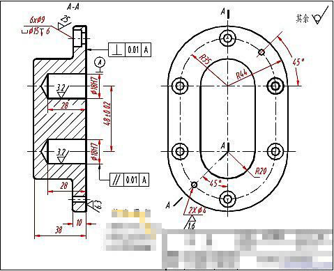
Disc Cover Parts:
The fixing and positioning dimensions of disc cover parts are obvious. Generally, the dimension datum in the length direction is the main machining surface (generally the contact surface of the part), and the datum in the width and height direction is the axis of rotation or symmetrical plane. The locating circle diameter of holes distributed on the circumference is a typical locating dimension of such parts.
See the pump cover in the figure below. The dimension datum in the length direction is the right end face (contact surface) of the pump cover. The dimension datum in the width direction and height direction are the symmetrical planes in the width direction and height direction respectively (the symmetrical centerline is shown in the projection drawing).
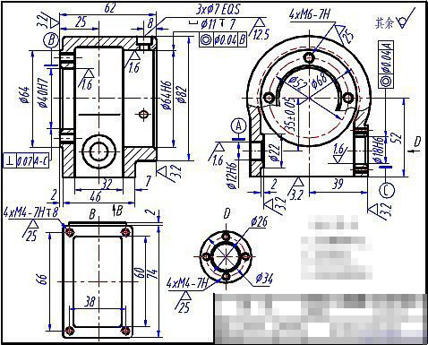
Box Type Parts:
For box type parts, the important mounting surface, contact surface, symmetry surface of the box and important axis are usually selected as the dimension datum. The setting size and positioning size are generally marked according to the shape analysis method. For the parts on the box that need to be machined, the dimensions shall be marked as far as possible to facilitate machining and inspection.
Take a look at the box parts shown in the figure below. The dimension datum in the length direction is Ф 12H6、 Ф The axis of the 18H6 worm shaft hole is the design datum, the dimension datum in the height direction is the installation bottom surface of the box, and the dimension datum in the width direction is Ф 40H7、 Ф The axis of the 64H6 worm gear shaft hole is the design basis.
Important Dimensions Must Be Indicated Directly
All dimensions on the parts that affect the performance, working accuracy and interchangeability of the machine are important dimensions. To ensure product quality, important dimensions must be directly indicated.
Any part has dimensions in three directions: length, width and height (or radial and axial directions). According to the design requirements, there can only be one main datum in each direction. However, considering the convenience of processing and measuring parts, the dimensions of parts in a certain direction can not always be indicated from one datum. As required, several auxiliary datums can be selected. At this time, there must be a connecting dimension between the main datum and the auxiliary datum.
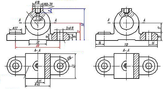
As shown on the left of the following figure, the dimension datum of the bearing pedestal in the height direction is the bottom surface, the dimension datum in the length direction is the symmetry plane, and the dimension datum in the width direction is the symmetry plane. The central height 32 of the bearing support hole is an important dimension in the height direction, and the distance 80 between the two mounting holes of the bottom plate is an important dimension in the length direction, which should be directly noted. For the convenience of processing and measurement, the top surface is used as the auxiliary datum to mark the screw hole depth dimension 8 on the top. Dimension 58 in the figure is the connection dimension between the auxiliary datum and the main datum. If the center height of the bearing support hole and the spacing dimension of the mounting hole are marked as dimensions 15, 17 and 16, 112 and 16, as shown in the right figure, the center height of the bearing hole and the spacing dimension of the mounting hole must be calculated, resulting in accumulated machining errors, which is difficult to ensure the accuracy design requirements of these two important dimensions, and may lead to the bearing pedestal not meeting the assembly requirements.
Avoid Injection Into Closed Dimension Chain
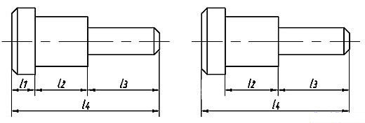
A group of chain like dimensions connected end to end is called a closed dimension chain. As shown in Figure 6 (a), dimensions l1, l2, l3, and l4 form a closed dimension chain. Each dimension that makes up the dimension chain is called the ring of the dimension chain.
From the perspective of processing, in a closed dimension chain, there is always a dimension that is naturally obtained after all other dimensions are processed. For example, after processing the dimensions l1, l2 and l3, the dimensions l4 are naturally obtained. Because the dimensions l1, l2 and l3 may produce errors during processing, these errors will accumulate to l4. If l4 itself has certain accuracy requirements, it cannot meet the design requirements. Therefore, when dimensioning, it should be avoided to note a closed dimension chain, that is, each ring should be noted with a dimension. Usually, the least important dimension in the dimension chain is taken as the opening ring, and the dimension is not marked, as shown in Figure (b). In this way, the manufacturing errors of other dimensions in the dimension chain are concentrated on the closed ring, thus ensuring the accuracy of important dimensions.
Of course, there are still many problems to be considered when dimensioning on the part drawing, such as ease of processing, measurement and assembly. The dimensions of the blank surface and the machining surface of the part should be marked separately. There can only be one contact dimension between the blank surface and the machining surface in the same direction.