


Contour milling is a common and important machining method in CNC milling. It is primarily used to remove material along a specified external or internal contour of a workpiece, thereby obtaining precise two-dimensional or three-dimensional shapes. Unlike conventional face milling, which is mainly used for planar material removal, contour milling places greater emphasis on the machining accuracy of workpiece edges, curves, shapes, and complex geometric contours.
In CNC machining, contour milling is widely used in aerospace, automotive, medical device, mold, robotics, industrial equipment, and the manufacturing of precision mechanical parts. Through reasonable tool selection, toolpath planning, and cutting parameter settings, contour milling can achieve high-precision machining of complex shapes and meet strict dimensional tolerances and surface quality requirements.
This article will introduce contour milling from its definition, machining principle, common types, machining process, tool selection, and practical applications to help readers gain a more comprehensive understanding of this CNC machining process.
What is Contour Milling?
Contour milling refers to the continuous cutting along a specified contour of a workpiece using a CNC milling machine or machining center, following a pre-programmed toolpath, to machine the desired external shape or internal boundaries.
The “contour” can be a simple straight line and arc, or a complex curve, inclined plane, or three-dimensional freeform surface. Depending on the part’s structure and machining requirements, contour milling can be used to machine both the external contour of a workpiece and the internal contours of holes, slots, cavities, etc.
In actual CNC machining, the CAD model is first imported into CAM software. Engineers formulate machining strategies based on the part’s geometry, material, dimensional tolerances, and surface requirements. The CAM software then generates the corresponding toolpath and converts it into a program that the CNC machine tool can execute.
During machining, the cutting tool moves along the specified path according to the program, while the cutting speed, feed rate, and depth of cut are controlled to gradually remove excess material, ultimately forming an accurate part contour.
What is the difference between contour milling and ordinary milling?
The biggest difference between contour milling and other CNC milling processes lies in the tool path and the machining target.
Face milling is typically used for rapid material removal or machining large flat surfaces, while contour milling focuses on machining around the boundaries and geometry of a part. For a part with a complex shape, face milling alone cannot achieve the final contour; contour milling is usually required to finish edges and curved areas.
Contour milling can also be combined with processes such as drilling, cavity milling, slot milling, and surface machining. By rationally arranging different machining operations, complex parts can be manufactured in a single setup or with fewer setups, thereby reducing positioning errors and improving overall machining efficiency.
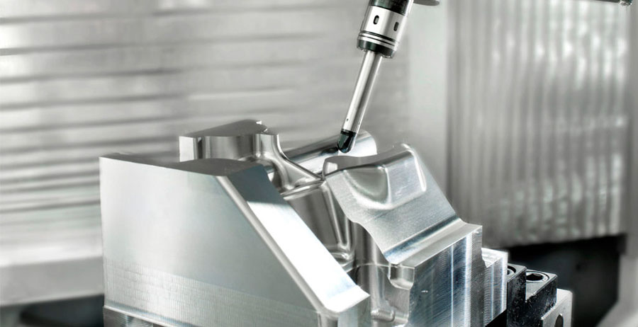
Basic Machining Flow of CNC Contour Milling
Contour milling typically begins with CAD models and engineering drawings. Engineers first confirm the overall dimensions, contour shape, material, and critical dimensions and tolerance requirements of the part, and then determine the machining process based on this information.
Next, appropriate CNC machine tools, cutting tools, and clamping methods need to be selected. For simple two-dimensional contours, a three-axis CNC machining center is usually sufficient. If the part contains complex curved surfaces, inclined structures, or contours in multiple different directions, four-axis or five-axis CNC machining may be required. In the CAM programming phase, engineers create toolpaths based on the contour shape. For parts with large blank allowances, roughing is typically performed first to quickly remove most of the material, followed by semi-finishing and finishing to gradually achieve the final dimensions.
The roughing stage focuses on material removal efficiency, while the finishing stage prioritizes dimensional accuracy, contour consistency, and surface quality. For high-precision parts, smaller diameter tools may be needed to machine detailed areas and corners.
After machining, the parts typically undergo dimensional inspection and visual inspection. For parts with high tolerance requirements, coordinate measuring machines (CMMs), height gauges, profilometers, or other precision measuring equipment can be used to verify the contour dimensions.
Common Types of Contour Milling
Depending on the object being machined and the tool movement, contour milling can be divided into different forms such as two-dimensional contour milling and three-dimensional contour milling.
Two-dimensional contour milling is mainly used for machining external contours on a plane, such as brackets, mounting plates, flanges, connectors, and mechanical structural parts. The tool typically moves along a specified path on the XY plane, and different depths of cut are achieved by controlling the Z-axis height.
3D contour milling is used to machine parts with complex spatial shapes, such as molds, impellers, aerospace structural components, and mechanical parts with free-form surfaces. In this type of machining, the toolpath is more complex and typically requires precise calculations using CAM software. For complex geometries, five-axis CNC machining can change the tool direction, thereby achieving better tool contact conditions and machining quality.
Depending on the machining location, contour milling can also be used for external and internal contour machining. External contours are mainly used to form the final shape of the part, while internal contours are often used for structures such as holes, slots, and cavities.
Commonly Used Tools for Contour Milling
Tool selection directly affects the machining quality and efficiency of contour milling. End mills are one of the most common contour machining tools, and different diameters, number of cutting edges, and coatings can be selected based on the material and machining requirements.
For non-ferrous metals such as aluminum alloys, carbide end mills with good chip removal capabilities are usually chosen to reduce chip buildup and improve machining efficiency. When machining harder materials such as stainless steel, titanium alloys, and tool steel, it is necessary to select carbide cutting tools with high wear resistance and heat resistance, and to appropriately reduce the cutting load.
In 3D contour machining, ball end mills are frequently used for surface finishing. Ball end mills can move along complex curved surfaces and create a more uniform surface quality. Round nose end mills are suitable for contour machining scenarios that require a balance between tool strength and surface quality.
The tool diameter also needs to be selected based on the contour dimensions. For large contours, larger diameter tools can be used to improve material removal efficiency; for narrow areas and small fillets, smaller diameter tools are needed to ensure the tool can enter the machining area.
Cutting Parameters in Contour Milling
Appropriate cutting parameters are crucial for ensuring the quality of contour machining. Cutting speed, feed rate, axial depth of cut, and radial width of cut all affect tool load, machining efficiency, and final surface quality.
If the cutting speed is too high, it may lead to tool overheating and rapid wear; if the feed rate is too low, it may reduce production efficiency and cause the tool to rub against the workpiece for an extended period. For materials with high hardness or difficult machining, cutting parameters need to be adjusted according to material properties to reduce vibration and tool load.
The finishing stage typically uses smaller cutting amounts and more stable feed parameters to obtain more accurate contour dimensions and better surface quality. For high-precision parts, proper control of finishing allowance is equally important.
Main Factors Affecting Contour Milling Accuracy
The final accuracy of contour milling depends not only on the CNC machine tool itself but also on multiple factors such as the tool, clamping, programming, and material.
First, the workpiece must have sufficiently stable clamping. If the workpiece moves or vibrates during machining, even if the CNC program is completely correct, it will be difficult to obtain an accurate contour.
Second, tool rigidity directly affects machining accuracy. Excessively long tools are prone to deflection and vibration, especially when machining deep cavities or deep contours. Therefore, within the machining range, the shortest possible tool extension length should be selected.
Furthermore, tool wear will gradually affect contour dimensions. If production batches are large, a reasonable tool change standard should be established based on the machining material and tool life to ensure consistency between different batches of parts.
For complex contours, CAM toolpath quality is equally crucial. A well-designed toolpath can reduce load variations caused by sudden changes in cutting direction and minimize vibration and machining marks.
Common Applications of Contour Milling
Contour milling is used in almost all CNC manufacturing fields requiring the machining of complex shapes.
In the aerospace industry, many aircraft structural components need to be as lightweight as possible while maintaining strength; therefore, CNC contour milling is often used to machine complex external contours and internal structures.
In automotive manufacturing, contour milling is used to produce engine parts, transmission parts, mounting brackets, molds, and various custom mechanical components.
In medical device manufacturing, contour milling can machine medical parts with complex geometries and stringent dimensional requirements, such as surgical instruments, medical device components, and some implantable device assemblies.
Furthermore, mold making is another important application area for contour milling. Mold cavities and cores typically have complex curved surface structures, requiring high-precision three-axis, four-axis, or five-axis CNC machining to achieve accurate geometry.
How to Improve CNC Contour Milling Efficiency?
Improving contour milling efficiency doesn’t simply mean increasing cutting speed; it requires optimizing the entire machining process.
First, the machinability of the part should be considered during the design phase. Excessively small internal fillets, excessively deep contours, and unnecessarily complex structures all increase machining difficulty and cost. DFM (Design for Manufacturing) optimization can reduce machining time without affecting part functionality.
Second, appropriate tools should be selected based on the material and part structure. Suitable tool diameter, number of flutes, and tool material significantly affect material removal efficiency and tool life.
Properly arranging roughing, semi-finishing, and finishing operations is also crucial. Roughing removes material quickly, while finishing leaves only a small machining allowance, thus avoiding the need for extensive material removal using finishing tools.
For complex parts, the appropriate use of four-axis or five-axis CNC machining can reduce the number of setups and improve the cutting angle between the tool and workpiece, thereby increasing machining efficiency and contour accuracy.
Advantages of Contour Milling
Compared to traditional manual machining, CNC contour milling offers significant advantages in accuracy and repeatability. Through digital program control, the same contour can be repeatedly machined dozens, hundreds, or even more times while maintaining a high degree of consistency in size and shape.
Contour milling also offers great flexibility. By simply modifying the CNC program and toolpath, it can quickly adapt to different part designs, making it ideal for custom parts, prototyping, and small-batch production.
Combined with advanced CAM software, multi-axis CNC machining centers, and high-performance cutting tools, modern contour milling can handle highly complex three-dimensional geometries and meet the high-precision requirements of industries such as aerospace, medical, automotive, and precision machinery.
Conclusion
CNC contour milling is an important manufacturing process for machining the external shape, internal boundaries, and complex three-dimensional contours of parts. Through appropriate tool selection, stable workpiece clamping, scientific cutting parameters, and optimized CNC toolpaths, production efficiency can be improved while ensuring machining accuracy.
From simple two-dimensional external contours to complex three-dimensional freeform surfaces, contour milling has a wide range of applications. For custom parts that require high precision, complex geometry, and stable batch consistency, the proper use of CNC contour milling technology can effectively improve product quality and reduce overall manufacturing costs.