

What Is Symmetry?
GD&T symmetry is a 3D tolerance that ensures that part features are symmetrical about the datum plane. The dimension defines a center plane and creates a tolerance zone around it. This tolerance is similar to concentricity, and the verification of symmetry tolerance is also time-consuming and difficult. It is generally recommended to use position, parallelism or straightness instead of symmetrical tolerance.
GD&T symmetric dimensioning ensures symmetry control by checking the distance between any two corresponding points on both sides of the datum plane and calculating their midpoint. These midpoints must be located near the datum plane and within the symmetrical tolerance zone specified in the feature control frame.
Symmetry Tolerance Zone
A parallel plane on the same side as the central datum plane. The midpoint of the symmetrical surface must all lie within this area.
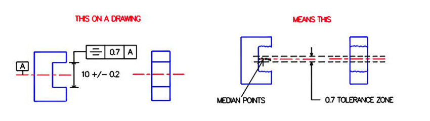
Examples of symmetrical tolerances are shown below. The figure above shows the symmetry symbol applied to the notch. The framed symbol can be understood as “the midpoint of these relative surfaces must be symmetrical about datum axis a within the tolerance range of 0.7”. The following figure shows an example section that meets this requirement. The midpoint must lie between two planes 0.7 apart and equally spaced around the datum axis A. All points on the median plane must lie within the volume between the two planes of the tolerance zone in order to be approved.
Symmetry vs Other Callouts
Symmetry and true position
Both symmetry and true position can be used to define the ideal position of part features. In some cases, they can even be used interchangeably. However, compared with symmetry, the use of real location is much wider. It can do everything symmetry can do, but the opposite is not the case.
True position annotation can establish a general wide tolerance zone and a circular area. This increases the range of functions it can control. Additional tolerances are allowed for true position and not for symmetry. Symmetry also does not allow datum feature offset and projected tolerance zone, both of which are possible in real position.
Another difference is that the real location can be called relative to feature size (RFs) or with minimum / maximum material conditions (LMC / MMC). Symmetry always applies to RFs.
Symmetry and concentricity
The concentricity dimension controls the concentricity of cylindrical surfaces, while the symmetry control is usually used for any non cylindrical surface. Some people call concentricity the circular version of symmetry. ASME Y14. 5m-1994, 5.14 states: “symmetry and concentricity control are the same principle, except for different component configurations.”
GD&T symmetry controls the points of the two options by developing the reference aircraft. On the other hand, the concentricity image checks the concentricity by establishing a central reference axis. It then gradually expands the true cylindrical cross-section centers and whether they are within the cylindrical tolerance zone close to the large datum axis. Concentricity derives the exact central axis rather than the middle plane.
How to measure symmetry
In all GD&T dimensions, symmetry is one of the more difficult dimensions to measure. The midpoint that must be within the tolerance zone is a derived feature, and there is no ready-made actual surface to measure. The symmetry symbol needs to calculate these midpoints and the features under symmetry control. This calculation requires a lot of time and skilled operators.
There are two main methods of measuring symmetry tolerance.
Use a caliper or micrometer
Using a coordinate measuring machine
Use a caliper or micrometer
Micrometers or calipers can be used in some cases where symmetry is simpler. However, the skill of the operator and instrument errors will affect the accuracy of such measurements, so this is generally not recommended.
Different instrument designs can be used for different forms and position measurement. They can measure dimensions effectively, but may not be so accurate when verifying the form. Another disadvantage is that this method requires manual recording of measurements.
Using a coordinate measuring machine
This is the most common way to measure symmetry. Coordinate measuring machine (CMM) only needs to touch the stylus with relative points to draw all midpoint. Compared with caliper or micrometer, this method provides relatively higher accuracy.
Initially, the CMM is set up to establish the theoretical center plane. Then, use CMM probe to measure both sides of symmetry to calculate the position of the midpoint. The positions of all midpoints along the length of the feature are compared with the datum plane. The inspector will approve the part as long as no midpoint exceeds the tolerance limit around the datum plane.
CMM records the measurement results. Although this method requires less operators, it is still relatively complex to obtain accurate results.
Final Notes:
Due to its specific functional requirements and measurement difficulty, symmetry should be avoided in most cases. With flatness, parallelism, and true position, you can find exactly the same constraints on the part, although more dimensions and measurements are required. However, since gauges can be used to measure the real position (if MMC is used), and flatness is automatically controlled by dimensions and measured directly from the surface, these can be controlled in one process and no timely CMM measurement is required.