

What does the formation of the milling surface depend on? The resulting milled surface may be an axial surface, a radial surface or a complex surface, depending on the type of tool and process used.
Tool Type For Milling Surface
01. Axially Generated Surface
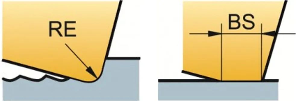
The shape of the bottom of the blade determines the quality of the resulting surface. The tool nose arc (RE) sometimes produces a cusp. The size of the spire depends on the arc radius and feed.
Inserts with parallel cutting edges (BS) can machine flat surfaces. According to the axial tolerance and runout of the milling cutter, the most protruding insert produces the final surface.
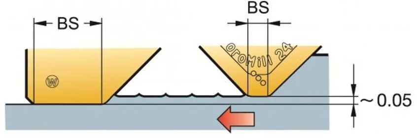
In order to produce the best milling surface quality, it is important to ensure that the feed per revolution (fn = fz×zn) is less than 80% of BS.
As the diameter of the milling cutter increases (and for ultra-dense-tooth milling cutters), the number of teeth and the feed per revolution increase, thereby requiring a larger BS. Once the feed per revolution exceeds the width of the parallel land, the axial runout of the milling cutter will affect the surface quality.
In order to obtain the best milling surface quality:
1) Use Wiper (wiper) inserts with BS at least 25% larger than fn or other milling inserts with wipers
2) The use of cermet blades can process a better finish
3) Use cutting fluid to avoid sticking
Wiper Blade
Wiper blades or long parallel blades can achieve larger diameter finishing. The wiper blade is higher than the standard blade to ensure that the wiper blade generates the final surface. The maximum fn should not exceed 80% of BS.
Round blade
Round blades or blades with large nose radius can achieve extremely high productivity, but cannot produce high-quality surfaces. The larger the diameter of the milling cutter, the worse the surface quality.
02.Radially Generated Surface
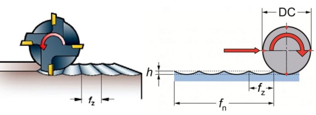
When using end mills, shoulder milling cutters, or face milling cutters, radial surfaces are generated. For surfaces generated in the radial direction, the profile is machined on the tool side edge.
Each tooth is machined with a tip (h), where the tip width is equal to the feed per tooth fz, and the tip depth is determined by the relationship between the diameter of the milling cutter and fz. The size of the spire obtained by theoretical calculation is the smallest.
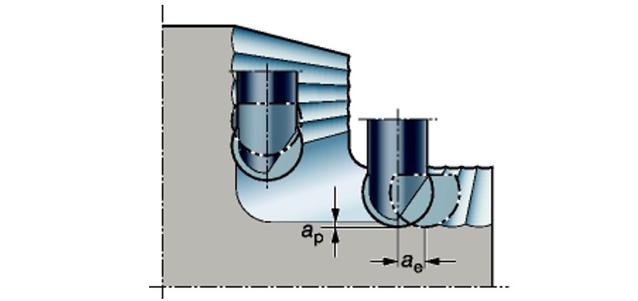
03. Complex Surface Generation
When using a ball end mill, a complex surface will be generated.
Process For Milling Surface
According to the surface milling method, it can be divided into three categories: tool tip trajectory method, forming tool method, and generating method.
The tool tip trajectory method relies on the motion trajectory of the tool tip relative to the surface of the workpiece to obtain the surface geometry required by the workpiece, such as turning the outer circle, planing the plane, grinding the outer circle, turning the forming surface with a master, etc. The trajectory depends on the relative movement of the cutting tool provided by the machine tool and the workpiece.
The forming tool method is abbreviated as forming method. It uses a forming tool that matches the final surface profile of the workpiece, or a forming wheel, etc., to process the forming surface, such as forming turning, forming milling, and forming grinding. Because of the difficulty in manufacturing forming tools, Therefore, it is generally only used for processing short forming surfaces.
The generating method is also called the hobbing method. It is the relative generating motion of the cutting tool and the workpiece during processing, and the instantaneous center line of the tool and the workpiece performs pure rolling with each other, maintaining a certain speed ratio relationship between the two, and the processed surface is The envelope surface of the blade in this movement, gear hobbing, gear shaping, gear shaving, gear honing and gear grinding are all part of the generative process. Some cutting processes have the characteristics of both the tool tip trajectory method and the forming tool method, such as thread turning.