

Although CNC machining still belongs to the category of metal cutting processing, it has its own characteristics. It is mainly realized as a high degree of automation, a long continuous machining process, and the time spent on tool setting is more complicated and time-consuming than traditional machining. Therefore, there are many questions worth thinking about in tool selection. This article brings you the relevant knowledge of CNC commonly used tools. I believe that a good tool is the first step to improve the efficiency of CNC machining.
Tool Material & Coating
Various tool materials currently in use have their characteristics to suit different processing requirements. The necessary properties of general tool materials include low friction coefficient, high precision, good thermal conductivity, sufficient toughness and impact resistance.
The common tool materials of traditional CNC machine tools are high-speed steel and cemented carbide. However, some special occasions such as high-speed cutting, dry cutting, cutting of difficult-to-machine materials, and turning instead of grinding require the use of superhard materials, including ceramics, CBN, PCBN, diamond, etc. The price of these superhard materials is relatively high, and the cutting process and parameters are not easy to master, and they have certain requirements on the rigidity of the machine tool, and there are not many applications in conventional processing.
Super Hard Material Tool
Tool surface coating is one of the important methods to improve tool performance, which has been widely used in recent years. Tool life with coating is ten times that of tools without coating. Common coatings include titanium nitride TIN, titanium carbide nitride TICN, and aluminum oxide. The following figure shows that the cutting speed of high-speed steel and cemented carbide has been shortened by a hundred times, while the use of coated tools has shortened the processing time by four times.
Tool Classification
Commonly used CNC tools are divided into three types according to their shapes: end mills, round nose cutters and ball cutters. Each tool has its specific role.
End Mill
The end mills of CNC machining centers are also called flat-bottomed cutters, which are surrounded by major cutting edges and the bottom is a minor cutting edge. The outer edge and bottom surface of the end mill have milling teeth to form the cutting edge, so it can be used to mill the vertical surface of the workpiece. The shape change of the end mill is very complicated, and it is suitable for all kinds of processing such as milling plane, groove, contour surface, etc. It can be said that it is the most widely used milling cutter.
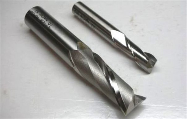
When milling a 2D-shaped workpiece, since the area in contact with the workpiece is the outer edge and the bottom surface, it is possible to use extremely efficient values for both the tool pitch and the cutting depth. However, when cutting the mold of a 3D workpiece, the contact area with the workpiece is almost always close to the sharp point. Therefore, the distance between the tools or the depth of cut must be reduced, which reduces the processing efficiency.
In short, end mills are suitable for 2D-shaped workpieces, but not for 3D-shaped workpieces.
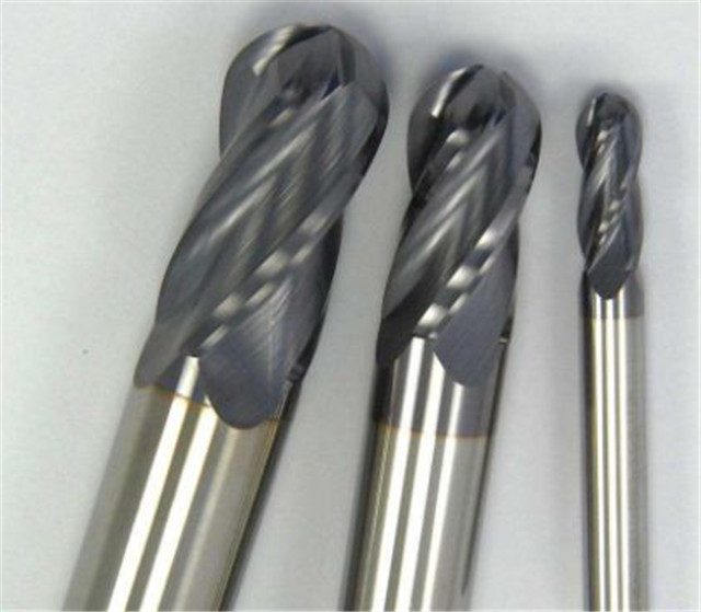
Ball Knife
The blade with a ball-shaped bottom blade is a ball knife, also called an R knife. In contrast to end mills, ball cutters are essential tools for milling 3D workpieces. Since the bottom of the ball knife does not have a sharp point like an end mill, but a blade with an R angle, the blade of the ball knife is more stable and not easy to collapse.
In mold machining, ball cutters are mostly used for milling 3D molds, especially in finishing and corner cleaning. However, the contact area between the spherical cutter and the workpiece is small, and the distance cannot be increased, so it is not suitable for milling relatively flat areas.
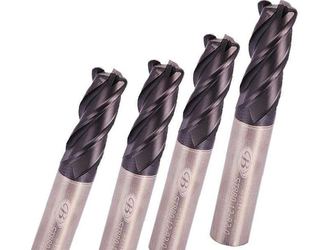
Round Nose Knife
The round nose knife of CNC machining center is also called flat-bottomed R knife, which can be used for roughing, flat smooth knife and curved surface contour smooth knife. Compared with end mills and spherical cutters, round nose cutters combine the advantages of the two and have better working efficiency. The horizontal knife spacing of the round nose knife can be larger than that of the ball knife, and it has the same advantages as the ball knife during finishing. Therefore, the round nose knife is a good choice for roughing or finishing.
If the workpiece is large, the surface change is small, the narrow recessed area is small, and the relatively flat area is large, it is best to use a round nose knife to process, and then use the secondary roughing method to find the area that needs subsequent processing. But facing some recessed areas, the round nose knife has a blind area of the blade, and the phenomenon of “top edge” will be found.
Common Problems And Solutions
In actual operation, there will always be various problems. Here are some common problems and solutions for everyone. I believe that as these problems are solved, the processing efficiency of machine tools will be improved.
Tool Vibration
As more and more difficult-to-process materials are used, vibration has become one of the obstacles to improving processing efficiency. The occurrence of vibration directly affects the machining accuracy and surface roughness, accelerates tool wear, severely affects tool life, and in severe cases, cutting work cannot continue.
Tool vibration requires three conditions that exist at the same time. The process system including the tool is not sufficiently rigid, resulting in low natural frequency. A sufficiently large external excitation force is generated during cutting. The frequency of the external excitation force is the same as the natural frequency of the process system. Resonance.
The idea of solving tool vibration is divided into three parts. The first is to reduce the cutting force to a minimum. To reduce the cutting force, use the smallest possible tip arc. Increase the rake angle of the tool. Replace pressed blades with ground blades. Reduce the depth of cut, speed and increase feed. Use an entering angle of 90 degrees for the elongated shaft. For milling cutters with slender rods, round inserts are most conducive to vibration reduction.
The second is to maximize the static rigidity of the tool system or fixture and workpiece.
The third is to create another vibration inside the tool bar to disrupt the vibration frequency of the externally excited cutting force, thereby eliminating tool vibration.
Blade Wear
During the machining process, the front and rear tool faces often wear out too quickly. Among them, there should be different response methods according to different blade damage conditions.
1. Excessive wear of the flank surface leads to rough surface and poor processing dimensions
Reasons for this scenario include high cutting speed or poor wear resistance of the blade. Solutions include improving methods to reduce the cutting speed, while gradually increasing the amount of cutting, using more wear-resistant blade materials or coatings, and try to use down milling instead of up milling.
2. Notch wear
After the blade groove is ground, it may be damaged and cause surface roughness and chipping. The reasons include the feed rate is too small; the milling material has a tendency to work hardening; the surface of the workpiece has oxide scale, etc. Faced with this situation, it is necessary to check the groove wear of the blade frequently with a nail.
3. Built-up edge when milling stainless steel and heat-resistant alloy
Milling sticky cutter is also called built-up edge, which makes the machined surface rough and burr. The falling off of the built-up edge will cause the rake face of the blade to fall off and the blade edge to collapse, and the secondary chipping of heat-resistant alloy workpieces will cause the edge to quickly collapse. The reasons for this kind of situation are nothing more than blunt cutting edge, negative rake angle, low cutting speed, too thin chip thickness, and poor chip removal.
The method to solve the built-up tumor is roughly based on “six steps.” The first step is to increase the cutting speed for stainless steel and aluminum alloy. The second step is to use physically coated blades or non-coated blades. The third step is to gradually increase the amount of cutting to achieve the best chip thickness. The fourth step, Prepare sufficient high-pressure coolant or air to prevent secondary chips. The fifth step is to use down milling instead of up-cut milling. The sixth step is to use pure mineral oil to wash the cutting area at low speed for heat-resistant titanium alloy and precipitation hardening stainless steel.
4.Blade breaks or hits a knife
There are many reasons for this kind of edge chipping. The blade material is too hard, the blade geometry is too weak, and the cutting speed used is too low, which may crush the cutting edge, resulting in uneven workpiece material or intermittent cutting.
In view of this situation, firstly, check whether the shim is broken and whether the blade screw is deformed and need to be replaced; secondly, the vibration factor should be eliminated, and the blade material with better toughness should be used, and the blade with strong edge should be changed; finally, the cutting speed should be increased to eliminate the edge The mouth may be crushed. (Related Post: Summary Of Machining Wear Problems And Solutions)