

Technical drawings (and the drawing process) are a way of transferring information between engineers and manufacturers. Technical drawings usually supplement digital CAD files to provide additional information. Engineering drawings use standardized language and symbols. This makes the understanding of the drawings simple, and there is almost no possibility of personal explanation.
This article introduces the basics of technical drawings, what are technical drawings, why they are needed, how to make drawings and what elements should be included in standard drawings.
What Is A Drawing?
Technical drawings help define and illustrate specific mechanical requirements and processes. They are engineering drawings dedicated to mechanical purposes.
These technical drawings help convey the problems and solutions encountered by mechanical engineers. These drawings can become an integral part of the project and help define the work that needs to be done. They help communicate complex processes and structures in a clear and concise way.
Unlike artistic drawing, engineering drawing must be very clear and almost unambiguous. Different people should not interpret the drawings differently, but should focus on conveying information in a simple way. This eliminates the risk of misrepresenting what the drawing is trying to explain, and ensures that everyone working on the project has a clear understanding of needs and expectations.
In the field of prototyping and manufacturing, we usually deal with certain subtypes of technical drawings, called engineering drawings, which contain information such as materials and completion requirements, part information, and (most importantly) 2D and 3D views of the part. The angle has dimensions and tolerances.
Why Do We Need Technical Drawings?
First, the technical drawing verifies the content contained in the CAD file, thus assuring the manufacturer that they are manufacturing what they need. The perfect connection between CAD and engineering drawings shows that there are no errors in the design. Once the part is complete, the drawing can be used as a reference during the inspection process.
Second, technical drawings can provide many other information not included in the CAD file. The information conveyed through technical drawings may include:
- Tolerances for specific functions
- Surface treatment requirements for specific surfaces
- Material requirements for specific components
- Internal thread or external thread
Third, technical drawings can play a legal role. They are part of the purchase order and therefore part of the contract: if the manufacturer fails to deliver the parts as specified, the customer can use the technical drawings as evidence of the unfinished design. On the other hand, as long as the technical drawings are followed, the manufacturer can be protected from liability.
Fourth, in addition, manufacturers generally prefer to receive technical drawings together with digital files because they can quickly evaluate various aspects of the part, such as the geometry, size, and potential cost of the part.
Finally, technical drawings are the only way to convey engineering instructions in the world: there is no ambiguity, no confusion, and no factors that may jeopardize the success of the project.
How To Make Drawings?
Engineering drawings can be created by traditional methods such as pen and paper, but more commonly they are created by CAD (computer-aided design) software.
why? Because most CNC systems used by machines can read information directly from files and generate cutting programs accordingly. Hand-drawn drawings will only add a lot of manual work to the manufacturing engineer.
Therefore, we actually have only one choice. Every engineer should use CAD (computer-aided design) software because it has many advantages.
Of course, you can use CAD to make engineering drawings from scratch. But the easier option is to create a 3D model first and create graphics from it, because the program can generate the view in just a few clicks. All you need to do is add dimensions. Owning the model can also easily update the drawing for revision.
Elements Of Standard Drawings
When preparing technical drawings for CNC machining, some specific functions may need to be added. These include:
Material
The materials used are an important part of the entire project. Engineering drawings must clearly indicate the materials used in each part of the project.
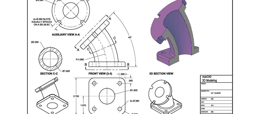
Geometry
Geometry involves the use of precise mathematical equations and graphics to generate the precise shape of the objects used in the project. This will help explain how different objects see them from different perspectives, and whether they can be combined appropriately. Using multiple views helps turn a one-dimensional engineering drawing into a clear and comprehensive blueprint.
Dimensions
The dimensions used in the drawing will help illustrate the dimensions of each object used. This helps provide scale for the project and ensures that everyone understands what each component looks like.
Mechanical engineering drawings may also be accompanied by notes and content specifically related to the drawing. This can help ensure that anyone reading the drawings fully understands the intent of this mechanical project.
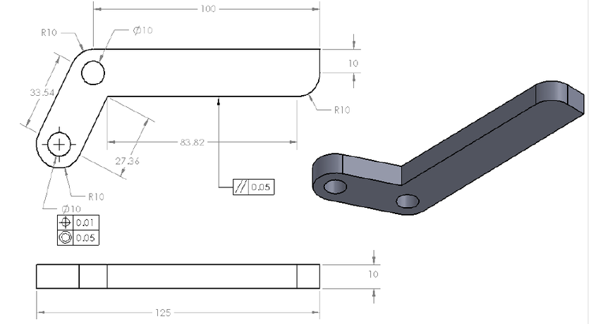
Tolerance For Specific Areas
CNC machining is different from other manufacturing processes because multiple machines can be used to process a single part. For example, machining can start with rough machining and then face milling to obtain detailed features. Therefore, engineers may specify different tolerances for different areas of the part and use finer cutting tools for slower machining of critical areas.
Hole Callout
Holes, including features such as countersinks, are common machining features of CNC and are usually marked in partial views.
Thread Specification
Since the threads are standard sizes, it is helpful to assign the relevant thread size to each thread instead of the size in millimeters.
SANS Machining has many years of rich experience and is good at small batch and multi-variety customized parts processing. Please upload The Drawing For Free Quotation.