

Drawings are the language used by engineering and technical personnel for communication. It is difficult for non professionals to read mechanical drawings, but for mechanical drawings, they cannot communicate without seeing through, so mechanical drawings are the knowledge that technical personnel must master.
Types Of Mechanical Drawings
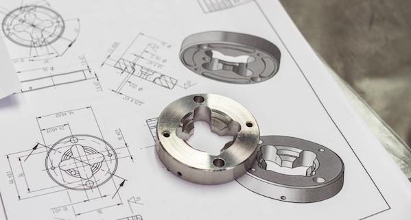
There are many kinds of mechanical drawings, including assembly drawings, sketches, schematic diagrams, part drawings, BOM, etc. first of all, you need to determine what drawing you get, so that you can know what object the drawing expresses, what aspects it expresses, and to what extent.
How To Understand Mechanical Drawings?
- First of all, it is necessary to clarify what type of drawings you get, assembly drawing, schematic diagram, or part drawing, BOM. Different types of drawings have different information and emphasis.
- First look at the object described in the drawing, that is, the title of the drawing; Although everyone and every company’s drawings will be the same, everyone basically follows the national drawing standards. A drawing is made to show people. If there are too many special places that others can’t understand, it will lose its meaning. So first look at the object name, number, quantity, material (if any), proportion, unit and other information in the title bar (lower right corner).
- Orient the view. Standard drawings have at least one view. The concept of view comes from the projection of descriptive geometry, so the basic concept of three views must be clear, which is the basis of reading the drawing. Understanding the relationship between the views on the drawing can basically understand the general shape of the product expressed in the drawing; According to the projection principle, the shape of the object can be expressed, and the object can be placed in any quadrant. Generally, the method of putting the object in the first limiting image to obtain the projection view is called the first angle projection method, so the second, third and fourth angle projection method can be obtained in the same way.
The first angle method is widely used in European countries (such as Britain, Germany, Switzerland, etc.), and the third angle method is the same as the direction in which we look at the position of the object, so the United States, Japan and other countries use this projection method; The Chinese national standard cnsb1001 stipulates that both the first angle method and the third angle method are applicable, but in the same figure, they cannot be used at the same time.
- The view corresponds to the key structure of the product. This is the key point of view, which requires accumulation and spatial imagination
- Determine the product size. We only need to take a general look at this and have a general concept. If it is a manufacturer, we will see it when it is used.
- Mechanical drawings (here are all standard product processing drawings) express all the design data used by the machinery industry, such as the structure, size, material, accuracy, etc. of a part or component or a machine. Before entering the industry, we have seen the material and structure parts, but there is still a lot of information in the drawings. Because almost all the mechanical information is in the drawings, there are thousands of pages of mechanical design manuals alone, Every dimension and expression in the drawing has certain stress, which means a lot of basic knowledge.
- Accuracy of products in the drawing: the mechanical dimension (such as the diameter of a cylinder) is not just a dimension. Whether the tolerance (± 0.xx) is marked or the dimension is not marked, it is a range, which is the mechanical (dimensional) accuracy. This concept should always exist. Because mechanical parts are generally produced in large quantities, precision is needed to control the size of each part (they can’t be the same size, and there must be errors in production) within a certain range. Similarly, there are geometric tolerances for components (both marked and unmarked). Unmarked accuracy (tolerance) is stipulated in national standards. Some drawings and technical requirements will state that accuracy is the soul of mechanical parts, which requires certain accumulation.
- The process of the product in the drawing: the process is simply the method of how to manufacture (assemble) this part. Although the mechanical drawing has no direct information expression of the process (process), it contains the basic process. It is meaningless for a part to be designed but not processed. How to process it must be something the designer has considered, and it will also be expressed in the drawing.
- Surface roughness of products in the drawing: roughness determines the use requirements and also limits the requirements for processing methods. Different processing methods can achieve different roughness. For example, the size, position, shape tolerance and roughness requirements of an element (an inner hole for bearing installation) will imply its processing technology requirements (grinding).
- Heat treatment of products: heat treatment makes the processing feasible, and the performance meets the use requirements. Heat treatment also has a certain relationship with the selected materials and processing technology.
- Surface treatment of products: surface treatment is generally put forward in the technical requirements, and surface treatment also has a certain relationship with materials.