

With the continuous development of modern manufacturing and machining technology, CNC machining equipment and its supporting CAM system have been widely used and developed. The machining tool trajectory generated by the CAM system (i.e. the tool path pattern) is the core of the control equipment’s machining operation. It directly affects the accuracy, surface roughness, overall machining time, service life of machine tools and other aspects of the machined workpiece, and ultimately determines the production efficient.
This article analyzes the different characteristics of the cutting method and some factors that affect its selection, and compares the technological methods and cutting methods in the milling process, and provides a reference for how to choose the appropriate tool path mode.
1. Tool Path Mode
The basic concept of the tool path mode.
In CNC machining, the tool path pattern refers to the path planning method when the tool completes the cutting of the workpiece. In the processing of the same part, multiple cutting methods can meet the size and accuracy requirements of the part, but the processing efficiency is different.
The classification of the Tool Path Mode
The tool path mode can be divided into 4 types: one-way feeding, reciprocating feeding, circular cutting feeding and compound feeding. The compound feeding is a mixed feed of the first three types. One-way or reciprocating feeding are all line cutting in terms of processing strategies. Therefore, according to the different processing strategies, the cutting method can be divided into line cutting, circular cutting and other special methods. Commonly used are row cuts and ring cuts.
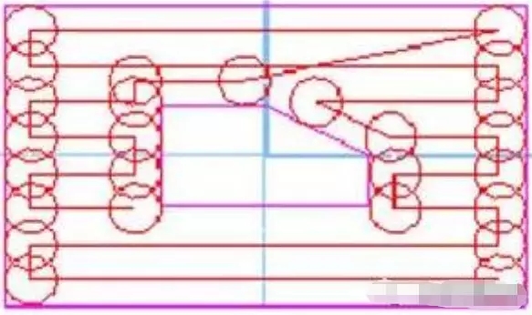
Line cutting is beneficial to the maximum feed rate of the machine tool, and the cutting surface quality is also better than circular cutting. However, when a complex plane cavity has multiple bosses to form multiple inner contours, additional tool lifting actions are often generated, that is, somewhere in the tool path, or to avoid interference between the tool and the boss, or To return the tool to the remaining unprocessed area, it is necessary to raise the tool to a certain height from the machining plane, and then translate to the beginning of another tool path, and then continue cutting.
The row cutting tool path is mainly composed of a series of straight line segments parallel to a certain fixed direction, and the calculation is simple. It is suitable for simple cavity finishing or rough machining with large margins removed.
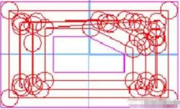
In ring cutting, the tool moves along a path with similar boundary contours, which is composed of a set of closed curves, which can ensure that the tool maintains the same cutting state when cutting parts. Since the loop cutting process is to calculate the next loop trajectory by continuously offsetting the current loop trajectory graph, the calculation is complicated and time-consuming. Suitable for the processing of complex cavities and curved surfaces.
2.The factors that affect the tool path mode
The shape and geometric elements of the workpiece
The shape and geometric elements of the workpiece include the geometric shape of the processing area, the size and location of the island, and so on. This is an inherent characteristic of the workpiece itself, and it is an unchangeable factor, but it is the fundamental factor that determines the way of tool feeding.
Routing
The process route is the direct process to achieve the processing purpose and the direct basis for the selection of the tool path mode. The process route determines the sequence of processing domains, the merger and splitting of islands, the division of rough machining, semi-finishing, and finishing. There are many process routes to achieve the goal, which determines the different choices of the tool path mode.
Workpiece material
The workpiece material is also one of the factors that determine the tool path mode. The material of the workpiece is the direct processing object and does not directly affect the tool feeding, but it will affect the selection of the tool material, size, processing method, etc., which indirectly affects the way of the tool. The shape and size of the workpiece blank will cause the distribution of the machining allowance of each part of the workpiece to be uniform. At the same time, for the workpiece with the optional blank, the use of the size and shape of the blank will change the clamping method and the redistribution of the processing area to affect the processing strategies, leading to a different approach to the tool feeding.
Workpiece clamping and fastening method
The clamping and fastening methods of the workpiece also indirectly affect the way of cutting, such as the influence of the new “islands” produced by the pressure plate, the effect of the tightening force on the cutting amount and the change of the way of cutting, and the impact of vibration on the way of cutting.
Tool selection
The selection of tools includes tool material, tool shape, tool length, number of tool teeth, etc. These parameters determine the area and frequency of contact between the tool and the workpiece, and thus determine the volume of the cutting material per unit time, the load of the machine tool, and the degree of wear resistance. And the tool life determines the length of the cutting time. Among them, the tool size (that is, diameter) has a direct impact on the cutting method. Since the selection of tools with different diameters will affect the size of the residual area, cause changes in the processing path, and lead to different cutting methods.
Machining Areas selection
In the milling process, when the complex plane cavity has multiple bosses to form multiple inner contours, additional tool lifting actions are often generated for line cutting, and the machining path is lengthened for circular cutting. This kind of additional tool lifting action or lengthening of the processing path will seriously reduce the efficiency of cutting processing. Therefore, how to minimize the number of such situations is a major issue we are concerned about.
Divide the entire cutting area into several sub-areas according to the processing needs, and process each sub-area separately. The tool lift takes place between the sub-areas. At the same time, these processing sub-areas are merged or divided according to the cutting method, or even ignored. This choice of different processing domains not only reduces the number of tool lifts but does not make the processing path relatively longer. At the same time, the most reasonable cutting method can be adopted for the new area, which improves the machining efficiency.
3. Reasonable Choice Of Tool Path Mode
Basic selection principle
There are two points to consider when choosing the feed method: one is the length of the processing time, and the other is whether the machining allowance is uniform. Generally speaking, the circular cutting method is a cutting method based on the shape of the workpiece, and the machining allowance is relatively uniform. However, the machining allowance of the row cutting method is relatively uneven. If you want to leave a more uniform allowance after the row cutting process, it is usually necessary to increase the circular cutting tool path around the boundary. If the requirement of margin unevenness is neglected, the path length of the line cutting tool is usually relatively short. If the unevenness of the margin is considered to increase the circular cutting tool path, when the processing area boundary is longer, the circular cutting tool path around the boundary has a more obvious impact on the total processing time, and the horizontal cutting tool path is generally better than the circular cutting tool path. long. The tool position of the row cutting tool is easy to calculate, and it takes up less memory, but there are more times of lifting the tool. When a circular tool path is used, it is necessary to offset the ring boundary several times and clear the self-intersecting loop.
Choose according to appearance characteristics
The shape characteristics of the workpiece determine the way of machining. According to the different processing objects, the workpiece can be simply divided into flat cavity type and free-form surface type. Plane-shaped cavities are generally processed by row cutting. Since most of this type of workpieces are formed by roughing and milling, such as boxes, bases and other parts, the machining allowance is large. The row cutting method is beneficial to maximize the progress of the machine tool. Feeding speed, improve processing efficiency, and its cutting surface quality is also better than ring cutting processing.
Free-form surfaces generally use circumferential cutting processing, mainly because the surface is mostly cast or formed from a regular shape, and the margin is not uniformly distributed. At the same time, the surface has higher requirements for the accuracy of the surface. It can approach the true shape of the surface better than having good surface processing characteristics.
Choose according to machining strategy
The processing of parts is often divided into three stages of roughing, semi-finishing and finishing, and sometimes there is a finishing stage. A reasonable division of the processing stages is necessary to ensure the accuracy of the processing. Traditional machining methods have relatively single functions of machine tools, so the boundaries of each stage can be clearly seen in the process route. However, the boundaries of the CNC milling processing methods are relatively fuzzy and may be mixed.
The main goal of rough machining is to pursue the material removal rate per unit time and prepare the geometric contour of the workpiece for semi-finish machining. Therefore, the row cutting method or the compound method is often used for layer cutting. The main goal of semi-finishing is to make the contour of the workpiece smooth and the surface finishing allowance is uniform. Therefore, the ring cutting method is often used. The main goal of finishing is to obtain workpieces with geometric dimensions, shape accuracy and surface quality that meet the requirements. According to the geometric characteristics of the workpiece, the internal cutting method shall be adopted, and the circular cutting method shall be adopted for the edges and joints.
Choose according to programming strategy
The main principles for determining the way of cutting during programming are: it should be able to ensure the machining accuracy and surface roughness requirements of the parts; the processing route should be shortened as much as possible, the idle movement time of the tool should be reduced, the numerical calculation should be simple, and the number of program segments should be small. Reduce programming workload. Generally speaking, for the plane-shaped cavity, the processing area is divided by the row cutting method to reduce the number of tool lifting, and the free-form surface circular cutting method approximates the shape. The selected size of the blank shape will affect the choice of programming. By increasing the shape of the blank, the shape processing that is not easy to be clamped can be converted into the easy clamping line-cutting method and cavity processing, or the free-form surface processed by ring cutting can be changed to line-cutting. Cutting way to a large margin to improve processing efficiency.