

GD&T Angularity Symbol
GD&T Angularity Definition
In the mechanical drawing of a part, angular tolerance allows the designer to specify the extent to which the orientation of the tilted part feature may change. A corner symbol is often used to ensure that a part fits correctly with another part. In GD&T, it helps to maintain a specified angle between a feature (line or surface) and a reference feature. It can be used to reference a line relative to another line, but more commonly, it is used to hold a surface at an angle to a datum or reference plane. This is particularly important for parts with sloping surfaces that mate with other parts in the assembly.
Angularity is also used to control the orientation of non-circular features, such as labels and grooves. Angular dimensions create a tolerance zone around the midplane to control these features.
Angularity Tolerance Zone
The biggest misconception about angles is that they create an angle tolerance zone, such as 30 degrees+/- 10 ‘. This means that the feature should be at an angle of 30 degrees to the reference plane and allow 10 minutes of angular variation on either side.
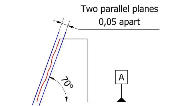
The shape of the tolerance zone varies with the controlled feature. In the case of curved surfaces, the tolerance zone is represented by two parallel planes that align with the exact angle required by the design.
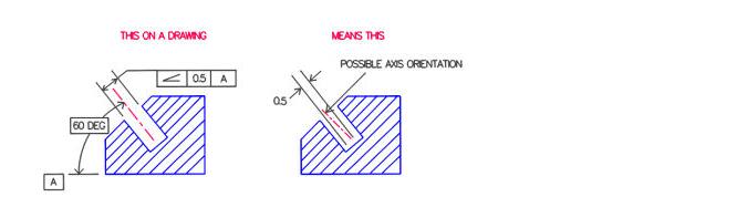
On the left side of the figure above, the angle symbol, tolerance, and datum in the box are used to control the center axis of the angled hole. The symbol in the box can be understood as “The axis must lie in two planes 0.5 apart, which are inclined 60 ° to surface A.”.
On the right side of the above figure, the tolerance zone created is represented by parallel lines.
This form of angular tolerance applies only to drawing views with specified tolerances and requires that allowable variations be defined for other views. However, if you place the diameter symbol in front of 0.5 of the bounding box, this creates a cylindrical tolerance zone that is then applied to all drawing views.
Angularity vs Other Callouts
Angle And Verticality / Parallelism
It has been noted that for the 90 ° and 0 ° angle cases, perpendicularity and parallelism are special cases of angle constraints. For example, this is considered an acceptable alternative in ASME standards. Because the concepts of “parallel” and “vertical” are usually easy to understand and recognize in printed materials, we usually recommend using these more specific controls as much as possible. When the design intent of the angle is very close but not completely 0 ° or 90 ° (that is, very subtle slope), this also allows the use of the angle to emphasize the difference more strongly.
Angle And Line Profile / Surface profile
Very powerful contour and surface contour controls can provide many of the constraints provided by other GD&T controls, but note that they are generally not interchangeable; For example, if the surface controlled profile has multiple or different datums, it will be different from the angle control (for example, it may not have the same degree of freedom). In general, corner control is more specific and legible in engineering printing.
Angularity And Flatness
At first glance, an angular constraint may look very similar to the tolerance of a flatness constraint, but note that the angular constraint is related to the actual implementation of the datum reference. If the surface is accidentally perpendicular, the flatness constraint on the horizontal surface can still pass! In the same case, angular constraints do not pass. The tolerance zone for angular constraints can be converted to achieve a best fit (thus determining pass/fail status), but it cannot be rotated.
Angularity And Angular Dimensions And Tolerances
When an angle tolerance frame is first encountered on a drawing, a common question is whether it is easier to use angular dimensions with positive and negative tolerances. Note, however, that the two are not equivalent. The definition of angle tolerance in the standard is not very clear, and there are still some differences when trying to give a clearer explanation. ASME standard describes two non parallel planes forming the tolerance zone, while ISO 14405-2 clearly stipulates that each angle inspection at any position on the surface is independent, and there is no parallel constraint between each position. If in doubt, use angle control, which allows additional datums, modifiers (such as tangent planes) to be included. This provides the ability to specify exactly the details required.
How To Measure Angularity
Check angle with dial gauge and sine bar Check angle with dial gauge and sine bar
Angularity keeps the flatness of the surface at a specific angle. Therefore, the method used to measure flatness can also be applied to angles, even at an angle. If all points in any direction (length and width) of the surface lie between two planes, the part is within the specified angular tolerance, which is called compliance with the specification.
For cylindrical regions, we derive the axis of the dimensional feature and ensure that it is completely within the region.
Metrology provides many options for measuring angles for both cases. From a more advanced perspective, optical comparators or CMMs are usually used. For mass production lines, the company may choose customized go/no go gauges.
The traditional method of measuring angles uses a sinusoidal plate. The inspected feature is inclined to the basic angle in the drawing, so it is horizontal and therefore parallel to the granite slab. Then, the machinist uses a dial indicator to check whether the flatness of the surface is within the allowable range.