

Doubts In Fixture Design
- Don’t know how to manufacture the designed fixture.
- The position accuracy and dimensional accuracy proposed in the fixture drawing, what means to ensure the realization.
- The fixture is manufactured in a single piece, and the design routine according to conventional products brings endless trouble to the accuracy of the fixture.
- The accuracy assurance method is the primary solution to the problem of fixture design.
Fixture Manufacturing Process Particularity
The primary purpose of using fixtures: to ensure the size (shape) accuracy and position accuracy of machined parts.
Workpiece manufacturing accuracy factors: In addition to machine and tool factors, machine tool fixtures must meet the design accuracy requirements.
Traditional fixture manufacturing process: The vast majority still use the assembly adjustment method. This fixture manufacturing process is like ordinary mechanical manufacturing. All parts are manufactured according to the part drawing and then assembled. The final fixture accuracy depends on trying to adjust or grind the position of a certain component. Or size to achieve.
Disadvantages of traditional fixture manufacturing: From the perspective of practical application, it is difficult to meet the various size and shape tolerance requirements of the assembly drawing.
Therefore, to ensure the accuracy of fixture manufacturing, special process methods must be adopted. The following 5 process methods ensure the accuracy of tool fixtures.
1. Group Processing Method
Method Definition:
It refers to processing the same structural elements on multiple elements at the same time when processing fixture elements. These structural elements are usually geometric size or cross-sectional shape, and the relative position between each other. The same processing conditions make it easy to guarantee the quality and interchangeability of fixture components, thereby improving the overall manufacturing accuracy of the fixture.
Method Classification:
According to different manufacturing methods, group processing can be divided into two specific process methods: “pair processing” and “mirroring processing”.
Paired Processing:
It means that all paired components in the fixture are processed in pairs by means of “combination grinding”, “combination boring”, “combination drilling”, “combination stranding”, etc., to eliminate dimensional errors and positions between workpieces deviation.
Practical Application:
preparation of positioning pins, boring of guide holes, grinding of contour blocks, etc.
Mirror Processing Method:
Refers to some fixture components with a symmetrical structure, which can be bounded by the symmetry surface, and the double length is first processed, and the workpiece with the equivalent margin is added, and then cut along the symmetry surface, and then after processing, use the mirror image principle Combine two symmetrical pieces to eliminate symmetry errors.
Case
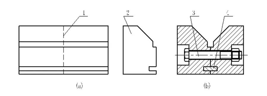
In the functional design of the V-shaped positioning block, it has an automatic centering function, and the accuracy of the symmetry of the two working slopes is very high. The traditional manufacturing method of the V-shaped block is generally an integral manufacturing. The final finishing of the two inclined surfaces is often done on a surface grinder using a precision sinusoidal fixture and a v-shaped guide magnet. But this processing method is very accurate to ensure that the v-shaped symmetry reaches the ideal state.
Practical Application:
When using the mirror image processing method, first make the V-shaped block into the semi-finished monomer as shown in Figure (a), cut it along the symmetry plane, and process the screw hole, and then use the orientation as shown in Figure (b). The key and the connecting bolt are assembled into a combined type V block.
Process Characteristics:
high precision machine tools are not required, but only with the help of ordinary machine tools, the symmetry of the V-block can achieve very high precision.
The Main Use:
Used in the manufacture of fixture elements with symmetrical structure or multiple pieces of repetition.
2. Clinical Processing Method
Method Definition:
It is to use the cutting function of the machine tool of the fixture to cut another part to eliminate the position error between each other, to ensure that each part occupies the ideal position, thereby improving the precision of the manufacturing of the center.
Process Characteristics:
Use the machine tool of the fixture to perform final processing to ensure fixture accuracy.
The Main Use:
It is used in the machining process of the positioning element of the fixture and used to ensure the final accuracy of the machine in the machine tool assembly.
Typical Application:
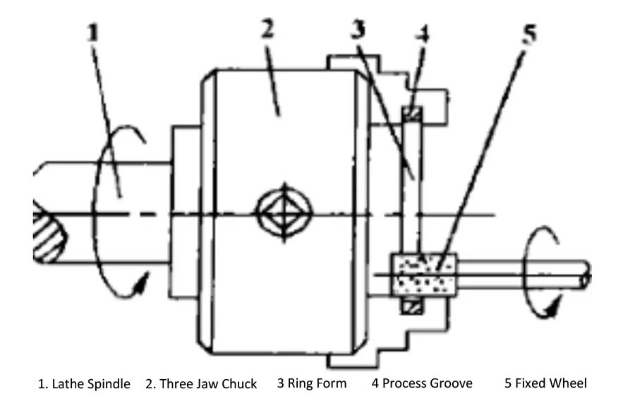
Grinding machine grinding external cylindrical shaft type fixture and grinding inner surface fixture, mandrel type fixture of lathe, working table of milling machine, electromagnetic chuck of surface grinder.
Technological Advantages:
Eliminate errors in the manufacturing, assembly and installation of fixtures, and finally obtain extremely high precision.
Conditions Of Use:
Clinical processing method, only machine tools with clinical processing conditions can be used.
Pattern Design:
When the designer requires the use of this process method to design the fixture, it should be noted on the fixture general drawing that “reserve the finishing allowance according to the size of the pattern to the final processing on the machine tool”.
3. Aligning And Fixing Method
The method of aligning first and then fixing usually uses general measuring tools.
Application Example:
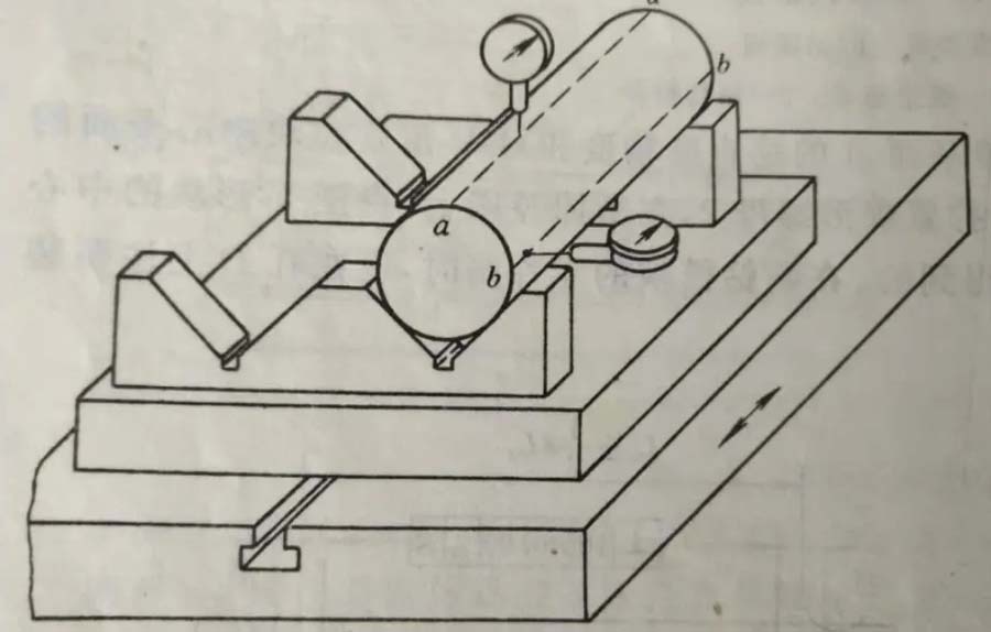
V-shaped positioning block is aligned and fixed, the directional key positioning groove and bolt installation on the ν-shaped fixed block have been processed.
Method Process:
Use a dial indicator to align the upper bus bar and the measuring bus bar of the mandrel, and make the mandrel parallel to the directional key surface (T-slot side) and the fixture installation datum plane. The alignment process requires repeated adjustment and grinding. After the alignment is completed, tighten the screws, drill the hinge fixing pin holes, and drive in the fixing pins.
Process Characteristics:
The accuracy of the alignment depends on the skill level of the workers, the accuracy of the measuring tools, and the accuracy of the measurement benchmark.
4. Transition Benchmark Method
Oblique holes and inclined surfaces with higher requirements are often encountered in fixture design. Due to the limitation of processing equipment, the inclined holes and inclined surfaces must be placed in a vertical or horizontal position to facilitate processing.
Due to the difficulty of measurement technology, it is impossible to directly measure and control its size during processing. Therefore, it is necessary to set the process reference hole as a transition reference to convert these sizes that need to be controlled into process sizes that can be directly measured or controlled.
Through the control of the transformed process size, the requirements of the design size of the workpiece are indirectly guaranteed. This process method is called the transition reference method, and it has been widely used in fixture manufacturing practice.
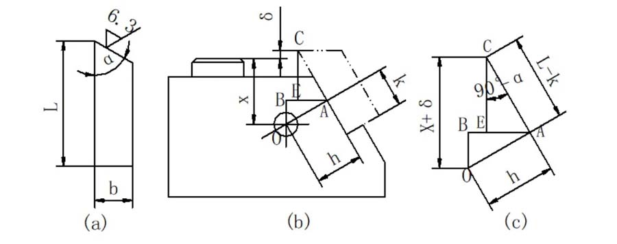
As shown in the above figure, under the premise of ensuring the dimensions h and K, as long as the working surface of the tool block is ensured to the axis X of the process reference hole O, the processing requirements of the long side dimension L can be guaranteed.
In addition, when processing some large boring dies on a boring machine, taking the process reference hole as the transition reference is an effective process method often used.
With this method, after the boring die is assembled as a whole, guide holes with higher coaxiality accuracy can be processed from both ends of the boring die in sequence. After the horizontal boring head has processed the guide holes on one end of the template, use the vertical boring head to machine two process reference holes on the two ends of the template. The center of the process reference hole should perpendicularly intersect the center line of the processed guide hole.
The boring die is turned around, and the process cylinder pin is assembled in the process reference hole, the dial gauge is clamped on the vertical boring head, and the beam is moved back and forth to correct the center position of the process cylinder pin at both ends. After calibration and fixing, the guide hole on the end template can be processed. Because the fixture is processed after being assembled as a whole, this method can ensure high coaxiality.
5. Assembly Processing Method
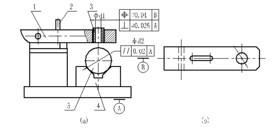
Design Requirements:
The verticality of the center axis of the inner hole φd1 of the drill sleeve to the installation reference plane A, and the position accuracy of the center plane of the V-shaped positioning block
Crafting Process:
On the coordinate boring machine, align the center plane of the V-shaped positioning block, tighten the wing nut after assembly, and bore the bottom hole of the bush on the drilling template.
Process Characteristics:
Relying on the accuracy of the coordinate boring machine, the position accuracy required by the fixture is directly guaranteed. It is the most effective method to ensure the verticality of the center axis of the drill sleeve and the fixture installation datum plane. The bottom hole of the guide sleeve of the drilling and boring fixtures used is processed by this process method.
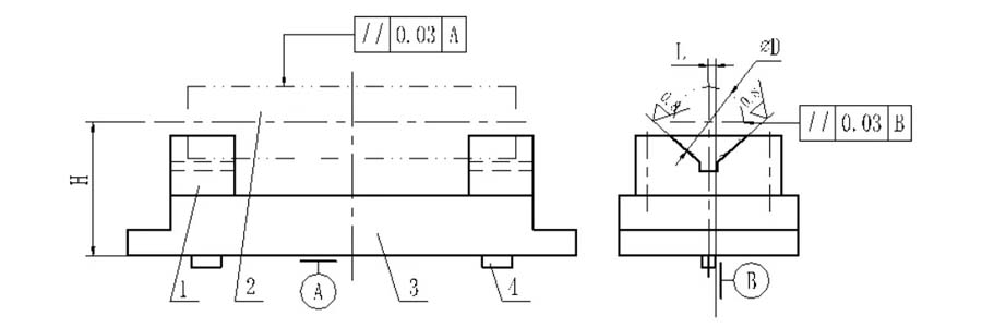
Design Requirements:
The position of the two V-shaped blocks is determined by the height dimension H and the horizontal dimension L, and the sides of the two directional keys are represented by reference B. The fixture design requires that the positioning surfaces of the two V-blocks must be in full contact with the workpiece, while ensuring the two parallelism requirements.
Process:
To ensure the parallelism of H, L and the two, when making the fixture, you can first make the two V-shaped blocks into a bevel, and leave enough semi-finished products with a grinding allowance, and assemble the V-shaped block to the clamp concrete. The tapered pin fixes both the V-shaped block and the clamp body.
On a tool grinder or rail grinder, using A and B as the positioning reference, the 90° inclined surface of the V-shaped block is ground to meet the requirements of H, L and two parallelism tolerances.
Notes
- When applying the assembly processing method for fixture design and manufacturing, you must be familiar with the characteristics of the manufacturing process of the assembly processing method, and meet this requirement in various aspects such as structural design, dimension and shape tolerance marking, fixture component processing and technical conditions formulation.
- Compared with traditional fixture design, fixtures manufactured by assembly processing methods have a big difference in pattern design. There should be four design patterns: fixture assembly drawings, fixture guide structures (such as drill sleeves, boring sleeves, etc.) assembly Product drawings such as processing drawings, pre-assembly drawings of fixture guide elements (ie semi-finished products), clamping mechanism and clamping details.
- The purpose of using these four patterns at the same time is to prevent the fixture manufacturing department from still using the process lines of making parts, assembling components, and adjusting accuracy during fixture manufacturing, whichcan guide and restrict the whole fixture manufacturing process.