

In the broad concept of industrial design, engineering drawing or technical drawing is an essential skill for designers to engage in physical production.
Engineering drawings use standardized language and symbols to accurately and visually communicate all the information needed to manufacture a product or part. This makes it easy to understand the drawings, with little possibility of personal interpretation.
What Is Engineering Drawing?
Engineering drawings, also known as mechanical drawings, manufacturing blueprints, drawings, etc., are technical drawings that express the shape, structure, size, tolerance, precision and other requirements of a part in the form of a plan view. It helps define requirements for engineering components and communicate design concepts.
Drawings can be used as a starting point for creating more comprehensive manufacturing drawings, manufacturing blueprints, mechanical drawings, dimension drawings, and more. Details about the drawing, such as who drew it and who approved it, are included in the title block or info box. It mainly consists of drawing actual components (such as machines) and their precise dimensions, and using entities such as points, lines, arcs, etc. The proportions of the dimensions are appropriately adjusted to properly fit the outline of the drawing.
Why Use Engineering Drawing ?
Drawings of individual parts provide a visual representation of the part’s construction, dimensions, tolerances, and other requirements. In the manufacturing industry, a single part drawing is often used as the processing unit.
Engineers can use assembly drawings to show a machine/equipment assembled from multiple parts to achieve a certain function. Assembly drawings are often used to verify that the actual production of individual parts meets assembly requirements.
As mentioned earlier, such technical drawings contain all the information for manufacturing a part or welding and building an assembly. This information includes dimensions, part names and numbers, etc. As a result, manufacturing engineers can start the production process without a second thought once they have the drawings.
Basic Components of Engineering Drawings
Title Block
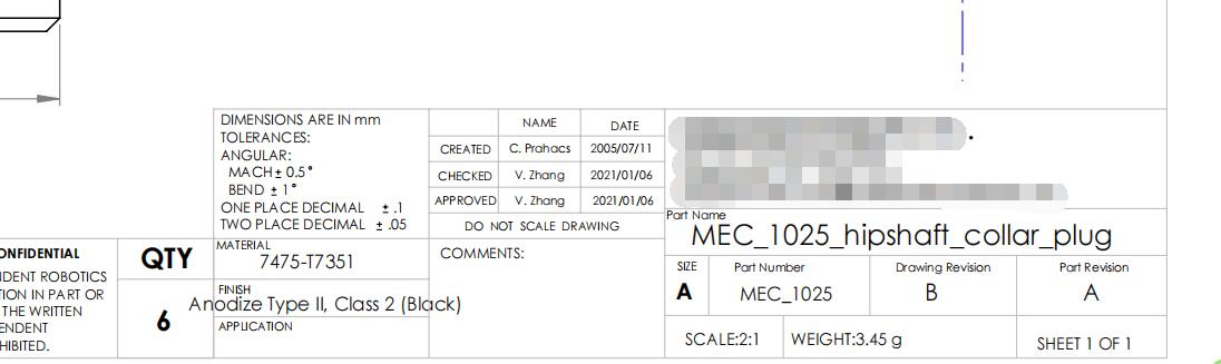
Begin by reading the title block in the lower right corner of the drawing. There are other similar blocks of information, but the title block is used as the context in which the drawing should be aware.
The document title in the engineering drawing block is located in the lower right corner of the page. Also known as an information block, it includes the part name, the name of the person who worked on the part (design, inspection and approval), company name, drawing number and other relevant information.
In addition, it includes technical details such as measurement units, projection angles, surface finish standards, proportions and materials of construction. Title blocks are used to better understand all parts of technical drawings.
Different Types Of Drawing Lines
Not every line on an engineering drawing is created equal. Different options can show visible and hidden edges, centerlines, etc. of parts.
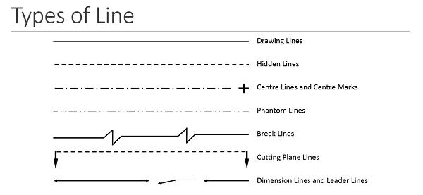
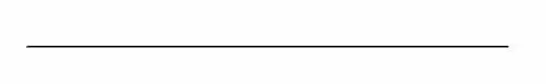
Continuous Line
Line drawing or continuous line is the most common, also known as line drawing. It is a visual representation of the physical boundaries of an object. In other words, use a continuous line to draw real objects. Use a variation of line thickness; thicker lines for outer contours and thinner lines for inner contours.
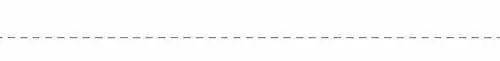
Hidden Line
Lines invisible to the naked eye can reveal information that would otherwise be hidden by design. The length of the internal steps of a turned part can use hidden lines instead of section or section views.
Centerlines Or Grid Lines On Drawings
You can display parts with holes and symmetrical features using centerlines. Symmetry reduces the number of dimensions in a drawing, making it more visually appealing and easier for readers to understand.

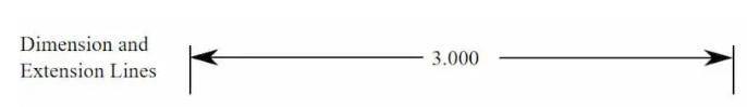
Dimension Line
The extension line annotates what is being measured. The dimension line has two arrows between the extension line and the top (or inside, as pictured below) of the measurement line.
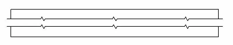
Broken View Lines
When the view is interrupted, the interrupt line appears. If you have a part that is 3000mm long and 10mm wide with symmetrical properties, using a splitter can provide all the information without taking up too much space.
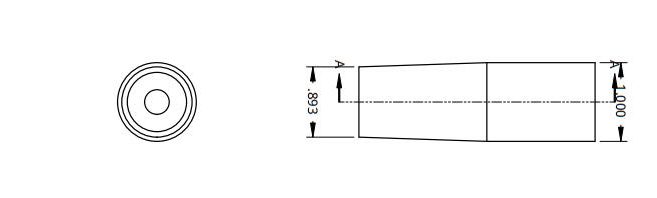
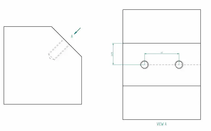
Cutting Plane Line
When using the clipping view, clipping plane lines show the trajectory of the clipping. In the image below, you can see that the A-A cut line brings both types of holes into view.
Types of Views
So let’s take a closer look at the different types of views that often appear in manufacturing drawings. Each has a specific purpose. Remember that adding views should follow the same logic as callouts – including as little and as much as necessary.
Orthographic View
Orthographic views are at the heart of drawing content. A 2D representation of a 3D object is called an orthographic view or orthographic projection.
Therefore, the 2D view must provide all the information required for part production. This representation avoids any length distortion.
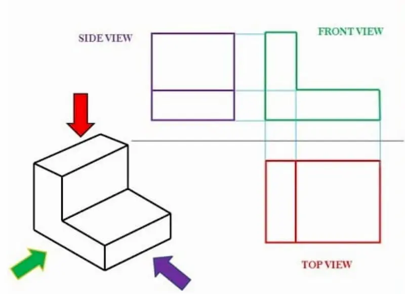
As the most common method of conveying all necessary information, a multi-view drawing usually consists of three views:
Front view
top view
side view
As you can imagine, showing all the information requires some additional views. less is more.
Isometric View
The image below is an example of an isometric view. Isometric drawings depict three-dimensional objects. All vertical lines remain vertical and parallel lines are depicted at a 30 degree angle compared to the front view.
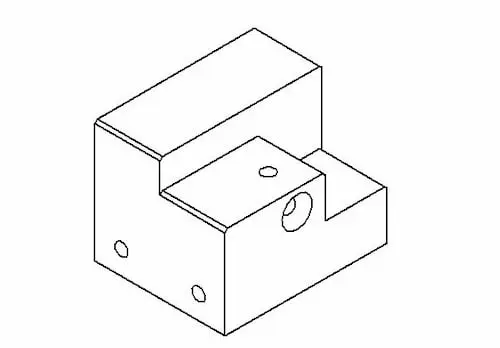
The vertical and parallel lines are their true lengths. This means, for example, that you can easily measure length directly from a paper drawing using a ruler and the scaling of the drawing. The same does not apply to angled lines.
It is important to understand the difference between isometric and perspective views. Engineers are loyal to size rather than optical illusion.
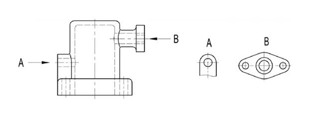
Partial View
A partial view is a view obtained by projecting a portion of an object onto the base projection plane. Use lettered arrows to indicate the part to be expressed and the direction of projection, and to indicate the name of the view. Local views can be configured in the form of a base view, or configured and tagged in the form of a configuration to a view.
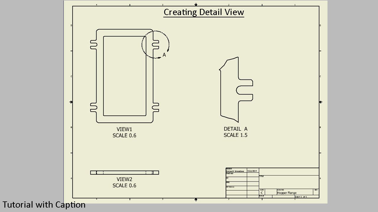
Detailed view
The detailed view gives us a close-up of a selected part of the larger view. This can be especially useful if a very large part contains many important dimensions in a small area. Using the detailed view can improve the readability of these measurements.
Auxiliary View
Auxiliary views are orthographic views of non-horizontal or non-vertical planes. It helps to render sloped surfaces without distortion.
Assembly Drawing
Many engineers’ drawings mistakenly attempt to include all the information about each individual part in the assembly drawing. To avoid this, keep in mind the purpose of these drawings in the creation process – they must make assembly easy.
Exploded views, section views, numbered parts, general dimensions, cutouts, detailed views (or close-ups) are all tools you can use to achieve this.
It should be clear where each part goes and how it is connected – whether it needs to be welded, bolted, riveted or otherwise. The bill of materials can help, so make sure the information provided there for the part number, name and quantity is correct.
Conclusion
Engineering drawings are still an important part of an engineer’s job, and engineering drawings are one of the best ways to communicate ideas and opinions. Making them takes about 20% of a design engineer’s work time.
Designers and engineers clearly map part features and communicate important information through drawings to help suppliers accurately capture critical information, understand design intent and develop machining solutions.