


CNC milling is an automated machining process that utilizes drilling, turning, and various other machining techniques. This is a machining technique that utilizes computer-controlled and rotating multi-point cutting tools to systematically remove materials from workpieces.
However, designers must first use CAD/CAM software to convert their concepts into digital formats before implementing their designs on CNC machines. Creating 2D or 3D designs that can be faithfully replicated requires a high level of detail and extensive simulation to maintain optimal accuracy. In addition, the created CAD files must be compatible with desktop milling machines to minimize errors and create high fidelity design prototypes.
This article will show you the considerations when preparing CAD models and the role of CAD models in CNC milling.
Key Considerations For CAD Model
Design Intent:
Understand the design requirements and intended functionality of the part. Consider factors such as material properties, tolerances, surface finish, and assembly requirements.
CAD Software:
Use professional CAD software like SolidWorks, Autodesk Inventor, or Fusion 360 to create your 3D model. These tools offer advanced features for precise modeling and manipulation.
Model Accuracy:
Ensure that the CAD model accurately represents the final part geometry. Pay attention to dimensions, features, and overall shape to avoid discrepancies during machining.
Feature Design:
Design the part with manufacturability in mind. Avoid complex geometries or sharp internal corners that may be difficult to machine. Use standard features like fillets and chamfers to improve tool access and reduce stress concentrations.
Tolerances and Fits:
Specify appropriate tolerances and fits for the part based on its function and manufacturing capabilities. Consider the CNC machine’s accuracy and the material’s shrinkage or expansion during machining.
Material Selection:
Choose the appropriate material for your part based on its mechanical properties, environmental factors, and cost considerations. Ensure that the CAD model reflects the chosen material accurately.
Toolpath Generation:
Once the CAD model is finalized, use CAM (Computer-Aided Manufacturing) software to generate toolpaths for CNC machining. Define cutting strategies, tool selection, speeds, feeds, and machining sequences based on the part geometry and material.
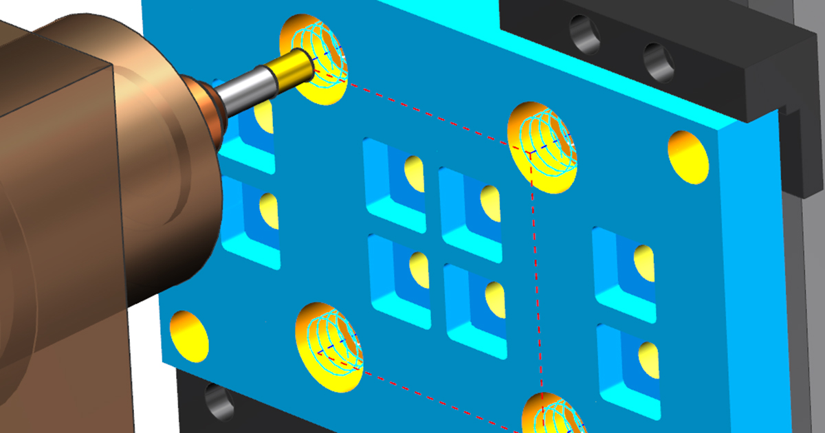
Machining Simulation:
Before proceeding with actual machining, simulate the toolpaths using CAM software or dedicated simulation tools. This helps identify any potential collisions, tool deflections, or machining errors that could affect the final part quality.
Post-Processing Considerations:
Consider any additional post-processing operations required after CNC milling, such as surface finishing, deburring, or heat treatment. Modify the CAD model as needed to accommodate these operations.
Documentation:
Provide comprehensive documentation along with the CAD model, including drawings, specifications, machining instructions, and any special considerations for the CNC machine operator.
The Role Of CAD Models In CNC Milling
CAD models play a fundamental and critical role in CNC milling, and are the cornerstone of the entire manufacturing process. The following is a comprehensive analysis of its importance:
Design and Visualization
Conceptualization: CAD models are the initial starting point for any CNC milling enterprise. Designers use CAD software to conceptualize and create detailed representations of expected parts or products for manufacturing.
Visualization: CAD helps designers envision the final product in a digital environment before actual production begins. This helps identify potential issues, make necessary adjustments, and ensure that the overall design meets the required specifications.
Geometric and dimensional accuracy
Accurate geometric shapes: CAD can create precise 2D and 3D geometric shapes, ensuring the accuracy of representing parts. This accuracy is crucial for CNC milling, as CNC milling typically requires strict specifications and tolerances.
Dimensional accuracy: Dimensional accuracy is crucial in CNC milling. CAD models provide basic information about feature dimensions, shapes, and positions to ensure that the final milled parts meet specified requirements.
Digital prototype
Testing and iteration: Before starting the actual CNC milling, designers can use CAD models to digitize the prototype design. This allows for virtual testing, identification of potential issues, and iterative design refinement to enhance functionality and efficiency.
Compatibility and Integration
CAM software integration: CAD models seamlessly integrate with CAM (computer-aided manufacturing) software. CAM software processes CAD models to generate tool paths and specifies the motion of CNC machine cutting tools during the milling process.
Material precautions: CAD models encapsulate information about material properties and characteristics. This information is crucial for selecting the appropriate milling tool, feed rate, and speed during the CAM programming phase.
DFM (Manufacturing Design) Precautions
Optimizing CNC milling: The CAD model is conceived based on the principles of DFM, ensuring that the design is manufactured using CNC milling technology. Designers can consider tool access, material limitations, and milling machine functionality during the CAD design phase.
Documents and Communication
Technical drawings: CAD models usually come with detailed technical drawings, providing additional information for manufacturing. This includes tolerances, surface finish, and assembly instructions, which help convey design intent to mechanics and other stakeholders.
Conclusion
The initial stage of CNC milling involves careful design of CAD models and requires careful consideration. When creating CAD for CNC milling, it is crucial to avoid thin-walled, excessively deep holes, and high aspect ratio threads. In addition, unnecessary mechanical processing, complex and small text on parts, and unrealistic geometric shapes such as curved holes and difficult to access features should be avoided. A carefully crafted CNC CAD model must have internal rounded corners and provide tool access to the entire part.