

The manufacturability analysis of CNC machined parts mainly includes three parts: part drawing analysis of the product, structural manufacturability analysis and part accuracy and technical requirements analysis.
(1) Part Drawing Analysis
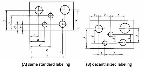
①The dimensioning method on the part drawing should be adapted to the characteristics of CNC machining. As shown in Figure (A), the dimensioning on the CNC machining part drawing should be marked with the same reference or the coordinate size should be directly given. This marking method not only facilitates programming, but also facilitates mutual coordination between dimensions, and is conducive to the unification of design benchmarks, process benchmarks, measurement benchmarks and programming origin. When dimensioning, part designers generally always consider assembly and other use characteristics more often, so they often use the partially scattered labeling method as shown in Figure (B), which brings a lot of inconvenience to process arrangement and numerical control processing. Due to the high accuracy of CNC machining and repeated positioning, the use characteristics of the parts will not be damaged due to large cumulative errors. Therefore, the local scattered labeling method can be changed to the same reference labeling or directly labeling the coordinate size.
②Analyze the design drawings of the processed parts, divide the processed surface into important surfaces and minor surfaces according to the marked dimensional tolerances and geometric tolerances and other relevant information, and find out the design benchmarks, and then follow the principle of benchmark selection to determine the processing The positioning datum of the part, analyze whether the blank of the part is convenient for positioning and clamping, whether the selection of the clamping method and clamping point will hinder the movement of the tool, whether the clamping deformation has an impact on the processing quality, etc. Provide basis for workpiece positioning, installation and fixture design.
③The conditions (such as tangency, intersection, perpendicularity, and parallelism) of the geometric elements (points, lines, and surfaces) that constitute the contour of the part are an important basis for CNC programming. In manual programming, the coordinates of each node must be calculated according to these conditions; in automatic programming, all geometric elements constituting the part must be defined according to these conditions. No matter which condition is unclear, the programming will not be possible. Therefore, when analyzing the part drawings, it is necessary to analyze whether the given conditions of the geometric elements are sufficient, and if any problems are found, they should be resolved through consultation with the designer in time.
(2) Structural Process Analysis Of Parts
①The inner cavity and shape of the parts should adopt uniform geometric types and sizes as much as possible, so as to reduce the tool specifications and the number of tool changes, facilitate programming, and improve production efficiency.
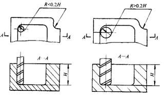
②The fillet size of the inner groove determines the size of the tool diameter, so the fillet radius of the inner groove should not be too small. For the parts shown in the figure below, the quality of its structure and craftsmanship is related to factors such as the height of the processed contour and the size of the corner arc radius. Figure (b) Compared with (a), the corner arc radius R is large, and an end mill with a larger diameter can be used for processing; when processing a plane, the number of feeds is also reduced correspondingly, and the surface processing quality will be better, so The manufacturability is better. On the contrary, the workmanship is poor. Generally, when R<0.2H (H is the maximum height of the contour surface of the workpiece to be processed), it can be judged that the workmanship of this part of the part is not good.
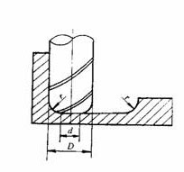
③When the part is milling the groove bottom plane, the groove bottom fillet radius r should not be too large. As shown in the figure below, the maximum contact diameter between the face of the milling cutter and the milling plane is d=D-2r (D is the diameter of the milling cutter). When D is constant, the larger r is, the smaller the area of the milling plane of the face of the milling cutter will be. The poorer the planar ability, the lower the efficiency, and the worse the manufacturability. When r reaches a certain level, it is even necessary to use a ball-end milling cutter, which should be avoided as much as possible.
④ As far as possible, the processing of all machineable surfaces should be completed in one clamping. For this reason, a positioning method that facilitates the processing of each surface should be selected; if a second clamping is required, a unified reference positioning should be adopted. If there is no uniform positioning datum in CNC machining, positioning errors will occur due to the reinstallation of the workpiece, which will make the contour positions and dimensions on the two faces after machining inconsistent. Therefore, to ensure the relative position after the secondary clamping process For accuracy, a unified positioning benchmark should be used.
3) Analysis Of Parts Accuracy And Technical Requirements
1) Analyze whether the parts accuracy and various technical requirements are complete and reasonable. For the surface processed by CNC turning, the accuracy requirements should be as consistent as possible, so that the final tool can be processed continuously.
2) Analyze whether the CNC machining accuracy in the process can meet the requirements of the drawings. Pay attention to leave enough machining allowance for subsequent processes.
3) Find out the surfaces with higher position accuracy in the part drawing, and determine whether these surfaces can be completed in one installation.
4) For surfaces or symmetrical surfaces that require high surface roughness of parts, determine to use the constant line speed function for cutting.
Thank you for sharing this informative article.