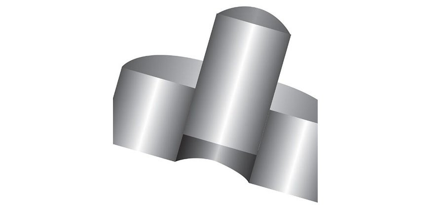
In the world of mechanical design, the successful interaction between mating parts is not left to chance; it is the result of meticulous calculation and careful specification. The relationship between a shaft and a hole, for instance, is defined by a “fit,” which dictates how they interact and whether they can move relative to each other. At the heart of this design philosophy lie Slip Fit and Press Fit—two fundamental concepts governed by a precise understanding of tolerance.
This expanded guide will delve deeper into these fits, exploring the underlying principles, their distinct characteristics, and the practical implications for manufacturing and assembly.
The Foundation: Unpacking Tolerance and Fit Systems
Before we can define slip and press fits, we must establish the role of tolerance. Tolerance is the permissible variation in a component’s dimensions, accounting for the unavoidable inaccuracies in manufacturing. Without it, mass production would be impossible.
To simplify the selection of fits, engineering standards like the ISO system have established two primary reference methods:
Hole Basis System: This is the most common system. The tolerance for the hole is kept constant, and the fit is achieved by varying the tolerance of the shaft. The hole is typically given an “H” designation (e.g., H7), which represents a zero lower deviation from the nominal size.
Shaft Basis System: In this less common system, the shaft’s tolerance is kept constant, and the fit is achieved by varying the tolerance of the hole.
By using these standardized systems, engineers can select a fit (e.g., H7/g6) from a chart, knowing precisely what the minimum and maximum clearance or interference will be, thus ensuring predictable and repeatable results.

Slip Fit (Clearance Fit): When Freedom of Movement is Key
A Slip Fit, also known as a Clearance Fit, is a relationship where the shaft is always smaller than the hole. This condition, guaranteed even at the most extreme ends of their respective tolerance ranges, ensures that a measurable gap, or clearance, always exists between the parts. This allows for relative motion.
Key Characteristics & Sub-Types:
Easy Assembly: Parts can be assembled and disassembled by hand with minimal effort, making this fit ideal for components that require regular maintenance.
Relative Motion: The clearance allows for rotational or sliding movement, which is critical for applications where parts must move against each other without seizing.
Common Sub-Types:
Loose Running Fit: Provides a generous clearance for parts that need to move freely, even with slight misalignment or thermal expansion. (e.g., H11/c11)
Close Running Fit: Offers a tighter clearance for more precise rotating parts that require good positional accuracy while still allowing for lubrication. (e.g., H7/h6)
Locational Clearance Fit: Designed to provide positional accuracy without significant motion, allowing parts to be easily assembled and disassembled. (e.g., H7/h6)
Common Applications: Bearings on a shaft, pulleys on an axle, sliding guides, and any component that needs to be easily removed for maintenance or replacement.
Press Fit (Interference Fit): Achieving Permanent, Secure Connections
A Press Fit, or Interference Fit, is the opposite of a slip fit. It’s a condition where the shaft is always larger than the hole, resulting in an intentional dimensional overlap called interference. When the parts are forced together, the interference creates internal stresses (hoop stress) that generate immense friction, locking the components in place and creating a robust, permanent joint.
Key Characteristics & Assembly:
Force Required: Assembly cannot be done by hand. It requires a significant amount of force, typically applied with a hydraulic press.
Thermal Assembly: A common, less forceful method involves heating the outer part (hole) to expand it or chilling the inner part (shaft) to contract it, allowing for easier assembly. The parts then return to their original dimensions, forming the interference fit.
Secure Connection: The friction bond is strong enough to transmit substantial torque and axial loads without the need for additional fasteners like keys, pins, or set screws.
Common Sub-Types:
Light Drive Fit: Used for parts that require a simple, semi-permanent connection and can be disassembled with moderate force.
Medium Drive Fit: The most common type for permanent assemblies, offering a strong joint for transmitting torque.
Force Fit: Provides the highest level of interference and is used for extreme loads, such as securing wheels on an axle for railway cars.
Common Applications: Attaching a gear or a pulley to a shaft, inserting a bearing outer race into a housing, and securing sleeves or bushings.
How To Assemble And Disassemble Press Fit And Slide Fit Components?
Best practices for assembly
Sliding fit requires minimal force for shaft hole assembly. The press fit mainly uses hydraulic presses to overcome any interference. During the assembly process, the two components should always be precisely aligned to avoid damage.
Safe disassembly techniques
Sliding fit is suitable for applications that require frequent disassembly, with good clearance for easy disassembly of parts.
For press fit, you need to use some mechanical force or thermal equipment to slightly modify the nominal diameter to eliminate interference.
Ultimately, selecting the correct fit is a direct reflection of the part’s functional requirements. A slip fit is chosen for dynamic, movable assemblies where ease of maintenance is a priority. A press fit is chosen for static, robust assemblies where a secure, permanent connection is paramount. A designer’s mastery of these concepts, and the tolerance systems that define them, is key to producing reliable, durable, and cost-effective mechanical systems.


