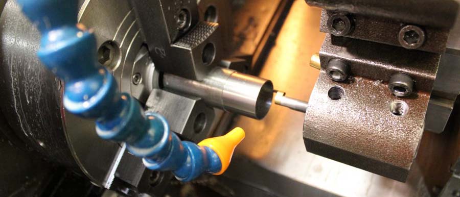
CNC turning is one of the most fundamental and efficient processes for manufacturing parts with cylindrical features. From simple pins and shafts to complex aerospace components, the lathe is the cornerstone of modern machining. However, the ultimate cost, quality, and lead time of a turned part are not determined on the shop floor—they are locked in at the design stage.
Adhering to Design for Manufacturability (DFM) principles is critical. A design that is functional but ignores the realities of the turning process will inevitably lead to higher costs, longer cycle times, and potential quality issues. This guide provides a set of practical, actionable best practices for engineers and designers to create parts that are not only functional but are inherently optimized for efficient and cost-effective CNC turning.
1. Simplify Geometry and Maintain Uniformity
The most direct way to reduce machining cost is to simplify the part’s geometry. Every feature, surface, and contour adds to the programming and machining time.
Minimize Feature Count: Each groove, taper, thread, or radius requires a specific tool and operation. By minimizing the number of distinct features, you reduce the number of required tool changes and shorten the overall cycle time.
Favor External over Internal Features: Machining on the outside diameter (OD) of a part is almost always easier and faster than machining on the inside diameter (ID). External turning allows for more rigid tooling, aggressive material removal, and easier chip evacuation. Internal work (boring) is constrained by the size of the hole and the length-to-diameter ratio of the boring bar.
Ensure Uniform Wall Thickness: Designing parts with very thin walls (e.g., less than 0.040″ or 1mm for metals) can be problematic. Thin walls are prone to vibration (chatter), deflection under tool pressure, and thermal distortion, making it extremely difficult to hold tight tolerances. Aim for robust and uniform wall thicknesses wherever possible.
2. Design Machinable Features
Certain geometric features are inherently difficult or expensive to produce on a lathe. A few smart design choices can avoid these common manufacturing pitfalls.
Radius All Internal Corners: This is perhaps the most critical DfM rule for turning. A standard turning insert has a rounded nose (a “nose radius”). It is therefore impossible for it to machine a perfectly sharp internal corner. Requesting a sharp corner forces the use of a secondary, much slower operation or a highly specialized, fragile tool. Always add a small radius to internal corners that is larger than a standard tool nose radius (a radius of 0.030″ or 0.8mm is a safe, generous value).
Standardize Threads: Use standard thread sizes (e.g., UNC, UNF, or Metric coarse/fine series) whenever possible. Designing a custom or non-standard thread requires expensive, specialized tooling and adds significant complexity to the setup. Additionally, it’s good practice to design a thread relief groove at the end of a thread. This small undercut allows the threading tool to cleanly exit the cut, ensuring a complete and well-formed final thread.
Avoid Deep, Narrow Features: The depth-to-width ratio of any feature is a key cost driver.
- Grooves:A standard O-ring groove is easy to machine. However, a very deep and narrow groove requires a long, slender grooving tool that is prone to breaking and chatter. As a rule of thumb, the depth of a groove should not exceed its width.
- Bores:A high length-to-diameter (L:D) ratio for an internal bore (e.g., > 10:1) is extremely challenging. It requires a long boring bar that is susceptible to deflection and vibration, making it difficult to hold tight tolerances and achieve a good surface finish.

3. Be Judicious with Tolerances and Surface Finishes
Unnecessarily tight specifications are the single largest driver of manufacturing cost. Every number on a drawing should have a clear functional justification.
Apply Tolerances Where They Matter: Apply tight tolerances only to critical functional surfaces, such as bearing fits, sealing surfaces, or locating diameters. All other non-critical dimensions should be left with a standard machine tolerance (e.g., +/- 0.005″ or +/- 0.125 mm). Adding another decimal place to a tolerance can exponentially increase the cost due to slower machining, multiple finishing passes, and increased inspection requirements.
Understand Surface Finish Callouts: A standard “as-machined” finish from a lathe is typically around 125 Ra µin (3.2 Ra µm), which is suitable for most applications. Requesting a smoother finish (e.g., 63, 32, or 16 Ra) requires slower feed rates, special tooling (like wiper inserts), and can significantly increase cycle time. Ultra-fine finishes often require expensive secondary operations like grinding or polishing.
Knurling:Knurling creates patterns on round parts for functional or aesthetic purposes. A knurled area should be narrow, and the width should not exceed the diameter.
4. Consider Material and Workholding from the Start
The manufacturing process begins with a bar of raw material and a way to hold it. These practical considerations should influence the design.
Make Use of Bar Stock Sizes and Shapes: Bar stock is the raw, purified material used in CNC turning. Its size and tolerance can often be advantageous when designing for screw-machine production.
Select Machinable Materials: The machinability rating of a material has a direct impact on the cutting speed and, therefore, the cycle time. Softer materials like 6061 aluminum, brass, or free-machining 12L14 steel are far easier and cheaper to machine than tough materials like 316 stainless steel, Inconel, or titanium.
Design for Standard Stock Sizes: Designing a part with an outer diameter that is just slightly smaller than a standard raw material bar size is highly efficient. This can eliminate time-consuming roughing operations needed to turn down a much larger bar.
Provide a Gripping Surface: The workpiece must be securely held in a chuck or collet. Ensure your design includes a sufficient length of a uniform, concentric surface for the machine to grip without damaging critical features. Avoid placing details right at the end of the part that could interfere with workholding.
Conclusion: A Partnership in Creation
Effective design for CNC turning is a collaborative effort between the designer and the machinist. A design that is created with an awareness of the manufacturing process will always be more robust, more consistent, and more economical to produce. By simplifying geometry, being mindful of feature design, using tolerances judiciously, and considering the physical realities of the shop floor, you can create parts that are not just functional on paper, but truly optimized for production.


