


Blind holes are one of the most common yet challenging features in machined components. Unlike through holes, blind holes do not pass completely through the material, which makes their design, machining, and inspection more demanding. Improper blind hole specifications can lead to tool breakage, poor thread quality, excessive machining time, or functional failure. This practical guide explains what blind holes are, how to machine them effectively, and what design considerations ensure reliable results.
What Is a Blind Hole?
A blind hole is a hole drilled or machined to a specified depth without breaking through the opposite side of the part. It is widely used when structural integrity, sealing performance, or aesthetic requirements prevent a through hole design.
Blind holes appear frequently in CNC-machined parts such as housings, brackets, molds, automotive components, and precision mechanical assemblies. They often contain internal threads, counterbores, or precise depth requirements, which increases their manufacturing complexity.
Key Design Considerations for Blind Holes
Depth-to-Diameter Ratio
One of the most important design factors is the depth-to-diameter ratio. As hole depth increases, chip evacuation becomes more difficult and tool deflection increases. A ratio of 2:1 to 3:1 is generally easy to machine, while deeper holes require special tooling and conservative cutting parameters.
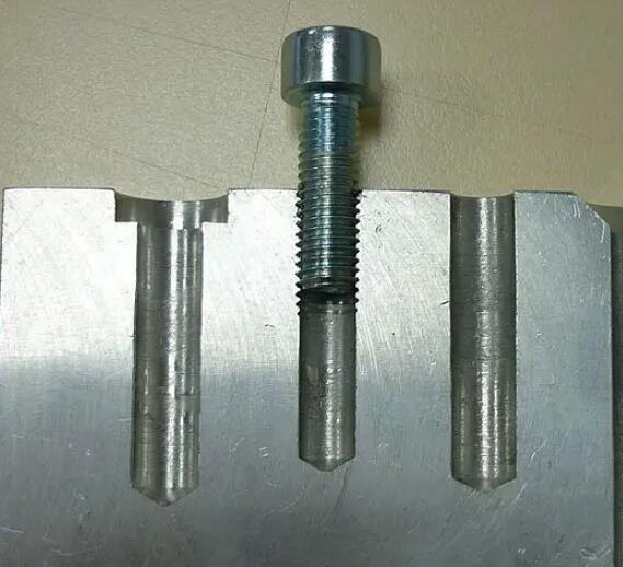
Bottom Geometry
Blind holes naturally have a conical or radiused bottom due to drill tip geometry. Designers should avoid specifying flat-bottom holes unless absolutely necessary. If a flat bottom is required, secondary operations such as end milling or specialized flat-bottom drills must be used.
Thread Depth and Relief
For threaded blind holes, additional depth beyond the functional thread length is essential. This extra space allows room for tool runout and chip accumulation. Without sufficient relief, threads may be incomplete or damaged.
Tolerance and Depth Control
Depth tolerances should reflect functional needs rather than excessive precision. Overly tight depth tolerances increase machining time and inspection cost without improving performance in most applications.
Machining Methods for Blind Holes
Drilling
Drilling is the most common method for creating blind holes. Peck drilling cycles help break chips and prevent tool jamming, especially in deeper holes or ductile materials.
Milling
End mills can produce blind holes with better positional accuracy and controlled bottom profiles. This method is often used for larger diameters or when precise location is critical.
Boring
Boring improves diameter accuracy and surface finish after drilling. It is ideal for blind holes requiring tight tolerances or alignment with other features.
Tapping and Thread Milling
Threaded blind holes require careful tool selection. Thread milling offers superior chip control and reduces the risk of broken taps, particularly in hard or brittle materials. Tapping remains efficient for high-volume production but demands proper depth planning.
Common Challenges and How to Avoid Them
Blind holes often suffer from chip buildup, poor surface finish, and tool breakage. Using appropriate cutting parameters, coolant delivery, and tool coatings helps mitigate these issues. For deep blind holes, high-pressure coolant and optimized chip evacuation strategies are essential.
Tool wear also becomes more critical due to limited visibility and access. Regular tool inspection and conservative feeds reduce scrap rates and downtime.
Common Measurement Challenges Associated with Blind Holes
Because blind holes feature enclosed bottoms, restricted access, and complex machining conditions, dimensional inspection often presents unique difficulties. These challenges become more pronounced as precision requirements increase.
Restricted Accessibility
Limited Depth Visibility:
Blind holes prevent direct visual or physical access to the bottom surface, which makes accurate depth verification difficult using conventional inspection methods.
Small Entry Diameters:
Many blind holes are narrow, leaving minimal clearance for probes or measuring instruments. This limitation increases the risk of incomplete contact or misalignment during measurement.
Limitations of Measuring Instruments
Accuracy Constraints of Standard Tools:
Basic instruments such as calipers or manual depth gauges often lack the resolution required for tight-tolerance blind hole measurements, especially in precision applications.
Tool Compatibility Issues:
Not all inspection tools are designed to work inside blind holes. Using unsuitable tools can result in partial data capture, inaccurate readings, or inconsistent results.
Influence of Hole Geometry
Complex Bottom Profiles:
Blind holes may feature flat bottoms, drill-point angles, or custom geometries. These variations complicate depth measurement and may introduce uncertainty if the probe does not properly reference the true bottom surface.
Surface Condition of Hole Walls:
Machining marks, surface roughness, or slight deformation along the inner walls can interfere with diameter measurement, particularly when using contact-based inspection methods.
Operational and Environmental Factors
Operator Dependence:
Blind hole measurement often relies on indirect techniques, which increases sensitivity to operator experience and handling consistency.
Environmental Effects:
External factors such as machine vibration, ambient temperature changes, or unstable setups can negatively affect measurement repeatability and reliability.
Interpretation and Reference Challenges
Indirect Data Evaluation:
Since blind hole features cannot be directly observed, inspectors must rely entirely on instrument readings, increasing the likelihood of misinterpretation if procedures are not clearly defined.
Reference Datum Selection:
Choosing an incorrect datum or reference surface during measurement can lead to cumulative dimensional errors, especially in depth or positional evaluations.
High-Precision Measurement Difficulties
Micro-Scale Blind Holes:
For very small diameters commonly found in micro-components or precision devices, standard inspection tools are insufficient. These applications often require advanced equipment such as micro probes, optical systems, or CMMs.
Non-Standard Hole Designs:
Blind holes with asymmetrical or custom geometries challenge conventional inspection approaches. In such cases, tailored measurement strategies or customized tooling may be necessary to achieve reliable results.
Inspection and Quality Control
Measuring blind holes requires specialized tools such as depth gauges, bore gauges, or CMM probes. Visual inspection alone is insufficient. Thread quality, depth consistency, and surface condition must be verified to ensure functional reliability.
Clear documentation of inspection requirements on drawings helps avoid ambiguity during production.
When to Consider Alternatives
In some cases, converting a blind hole into a through hole simplifies machining and reduces cost. If design constraints allow, this option should be evaluated early. For extremely deep or high-precision blind holes, EDM machining may provide better results than conventional cutting methods.
Conclusion
Blind holes play a critical role in modern machined components, but they require thoughtful design and careful machining. By considering depth, geometry, tolerances, and machining methods early in the design stage, engineers can reduce manufacturing risk and improve part quality. A practical approach to blind hole design ensures efficient production, reliable performance, and consistent results in CNC machining.