


Blind holes are widely used in machined components where structural integrity, sealing, or assembly requirements prevent a through-hole design. While common, blind holes often introduce complexity in both manufacturing and inspection. Poorly defined drawing notes or overlooked measurement constraints can lead to production delays, inconsistent quality, and increased cost. A well-considered blind hole design must balance functional intent, machinability, and inspectability.
Key Drawing Notes for Blind Hole Design
Clear and realistic drawing specifications form the foundation of successful blind hole manufacturing. One of the most critical points is depth definition. Designers should specify functional depth rather than absolute drill depth whenever possible, allowing reasonable tolerance for tool runout and bottom geometry. Overly tight depth tolerances often increase machining time without improving performance.
Bottom geometry should also be addressed carefully. Standard drilling naturally produces a conical bottom, and this should be accepted unless a flat bottom is functionally required. When flat-bottom holes are necessary, drawings should clearly note the machining method or allowable corner radius to avoid ambiguity during production.
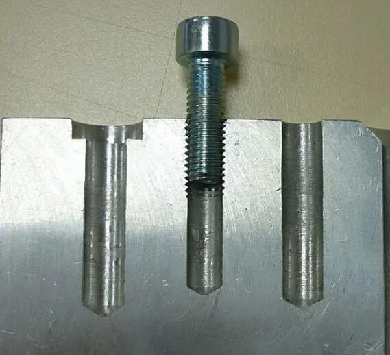
For threaded blind holes, drawings should distinguish between full thread depth and total hole depth. Additional clearance below the last usable thread is essential for chip accumulation and tool exit. Failing to specify this relief often results in incomplete threads or tool damage.
Datum references and positional tolerances should be selected with inspection in mind. Referencing inaccessible surfaces or internal features may complicate measurement and reduce repeatability during quality control.
Measurement and Inspection Challenges
Blind holes present inherent inspection difficulties due to limited accessibility and invisible bottom surfaces. Depth measurement is often indirect, requiring probes, depth gauges, or CMMs rather than direct visual confirmation. Narrow diameters further restrict tool access, increasing the risk of misalignment or incomplete contact.
Internal surface conditions also affect measurement accuracy. Roughness, tool marks, or slight deformation along the hole wall may influence diameter readings, especially when contact-based gauges are used. Bottom shape variations can lead to inconsistent depth measurements if the probe does not seat correctly on the true reference surface.
High-precision blind holes introduce additional challenges. Small diameters and tight tolerances frequently exceed the capability of standard inspection tools, requiring advanced metrology equipment and experienced operators. Data interpretation becomes more complex when measurements rely entirely on indirect readings rather than visual confirmation.
Practical Solutions and Best Practices
Effective blind hole design begins with design-for-inspection thinking. Engineers should define tolerances based on functional requirements rather than idealized geometry. Allowing reasonable depth variation and accepting standard drill-point bottoms significantly improves manufacturability and inspection reliability.
During machining, selecting appropriate cutting strategies—such as peck drilling, high-pressure coolant, or thread milling—reduces chip accumulation and improves dimensional consistency. For threaded blind holes, thread milling often provides better depth control and reduces the risk of broken taps.
From an inspection perspective, choosing the right measurement method is essential. Coordinate measuring machines, depth probes with defined reference surfaces, and optical measurement systems offer higher accuracy for blind hole evaluation. Clear inspection instructions and datum definitions on drawings help minimize operator-dependent variation.
In cases involving micro blind holes or non-standard geometries, customized inspection solutions or process validation through first-article inspection may be necessary to ensure consistent quality.
The Criticality of Blind Holes
Blind-hole design and machining directly determine product functionality and quality. Typical examples:
- In electronic enclosures, blind holes conceal connectors while preserving cosmetic continuity.
- In precision mechanisms, they provide datum features for accurate location and ensure stable, vibration-free operation.
Through rigorous design and process control, blind holes have become an indispensable element of modern manufacturing. Equally critical is their metrology: dimensional, geometrical and surface-verification data drive part function, assembly accuracy and overall product integrity. Key aspects are summarised below.
Securing Function And Performance
Fastener seating: blind holes accept screws, dowels or helical inserts. Diameter, depth and positional tolerances must be held to guarantee joint preload and prevent self-loosening under cyclic load.
Fluid/cable routing: when the hole acts as an internal gallery or wire-way, size and depth must match drawing call-outs to maintain specified flow rate or bend-radius requirements.
Meeting Assembly Accuracy
Mating-part alignment: even micron-level deviation in blind-hole true-position can cause stack-up misalignment, shortening service life or causing jamming.
Rework avoidance: inadequate in-process gauging leads to selective assembly or scrap, driving up cost-per-part.
Enhancing Reliability And Durability
Stress distribution: undersized or mis-located holes create stress risers that initiate fatigue cracks under repeated loading.
Sealing integrity: for sealed circuits (e.g., hydraulic valve bodies or pneumatic manifolds), dimensional or surface-finish error compromises O-ring squeeze, causing leakage.
Controlling Productivity And Cost
First-pass yield: on-machine probing and post-process CMM verification catch defects early, eliminating secondary operations and reducing PPM scrap.
Process standardisation: repeatable blind-hole measurement supports SPC, allowing high-volume production with Cpk ≥ 1.67 and ensuring lot-to-lot consistency.
Satisfying Industry And Customer Requirements
Compliance standards: aerospace (AS9100), medical (ISO 13485) and automotive (IATF 16949) all impose tight blind-hole tolerances; dimensional reports are mandatory for PPAP/FAIR submissions.
Customer confidence: delivering parts that conform to GD&T call-outs strengthens supplier rating and brand reputation.
In summary, blind-hole metrology is not a discretionary operation—it is a value-adding control point that underpins functional performance, assembly integrity and contractual compliance in precision machining.
Conclusion
Blind holes require more than basic dimensioning to achieve reliable manufacturing results. Thoughtful drawing notes, realistic tolerances, and inspection-aware design decisions reduce production risk and improve consistency. By addressing measurement challenges early and applying practical solutions throughout machining and inspection, engineers can ensure blind holes meet both functional and quality expectations without unnecessary cost or complexity.